1. Introduction
This manual provides essential information for the safe and efficient operation of the AUTONICS MT4N-DA-EN DC Amps Meter. Please read this manual thoroughly before installation, setup, and operation to ensure correct usage and to prevent potential hazards or product damage. Keep this manual in an easily accessible location for future reference.
2. Safety Information
Observe all safety precautions to ensure safe and proper operation. Failure to follow these instructions may result in electric shock, fire, or product damage.
- Ensure power is disconnected before wiring or performing maintenance.
- Do not disassemble or modify the unit.
- Install the unit in an environment free from excessive vibration, dust, moisture, or corrosive gases.
- Use the specified power supply voltage (12-24 VDC).
- Connect wires correctly according to the wiring diagram.
3. Product Overview
The AUTONICS MT4N-DA-EN is a compact 1/32 DIN digital panel meter designed for precise DC current measurement and indication. It features a 4-digit LED segment display and supports 0-500mADC input. This meter is ideal for various industrial applications requiring accurate current monitoring.
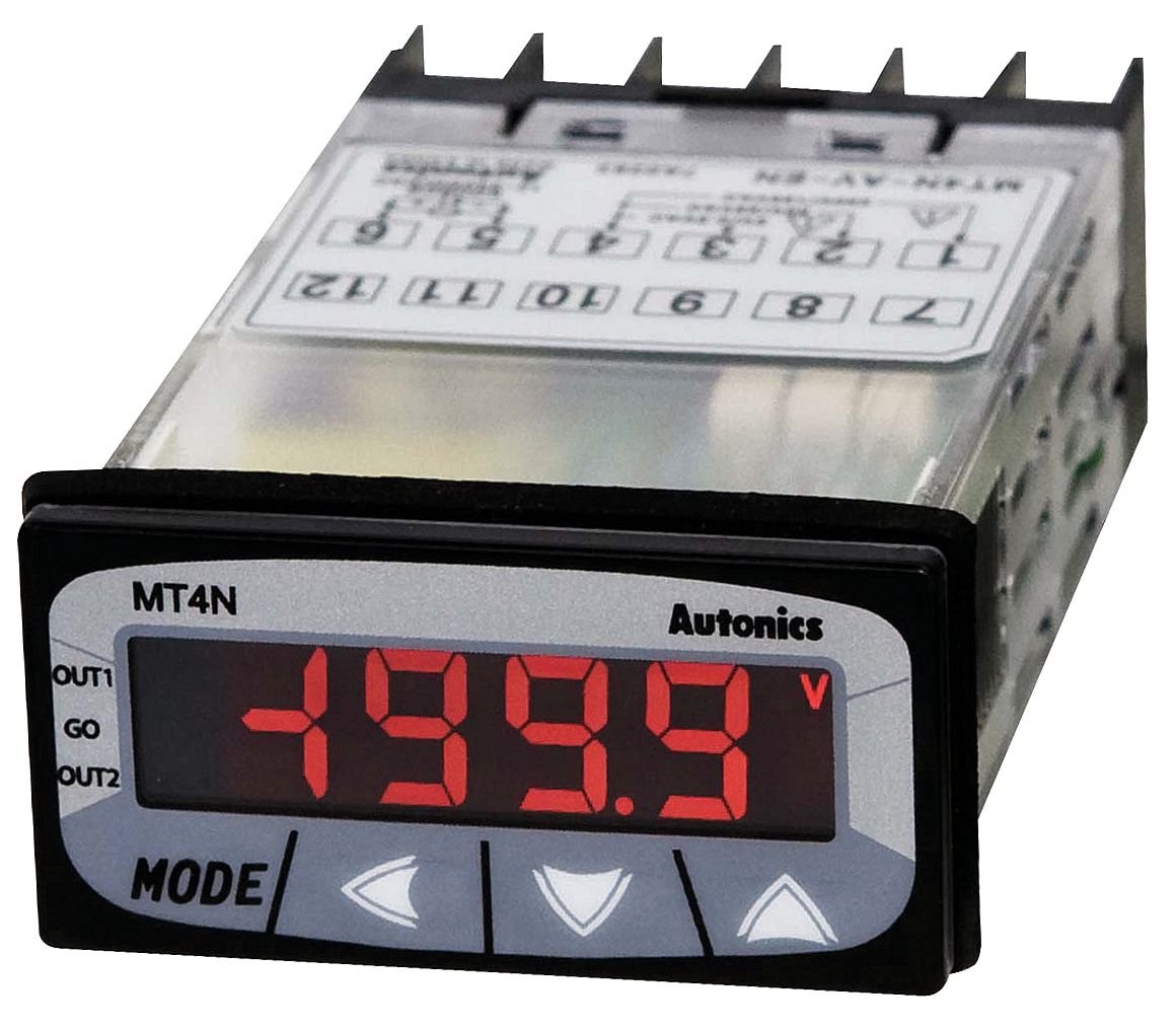
Figure 1: Front view of the AUTONICS MT4N-DA-EN meter, showing the 4-digit red LED segment display, "MT4N" branding, "Autonics" logo, and control buttons (MODE, left arrow, right arrow, up arrow). The display currently shows "-199.9". The top of the unit shows a partial wiring diagram with numbered terminals (e.g., 1, 2, 3, 4, 5, 6, 7, 8, 9, 10, 11, 12) and labels like OUT1, GO, OUT2.
3.1. Key Features
- 4-Digit LED Segment Display for clear readings.
- Input Range: 0-500mADC.
- Compact 1/32 DIN size.
- Power Supply: 12-24 VDC.
- Indication Only functionality.
4. Setup and Installation
4.1. Mounting
The MT4N-DA-EN is designed for panel mounting. Cut a panel opening of appropriate dimensions (refer to specifications for exact cutout size). Insert the meter into the opening and secure it using the provided mounting brackets.
4.2. Wiring
Ensure all power is OFF before proceeding with wiring. Refer to the wiring diagram on the unit or in the full product manual for specific terminal connections. The general connections are as follows:
- Power Supply: Connect 12-24 VDC to the designated power terminals. Observe polarity.
- Current Input: Connect the DC current source (0-500mADC) to the input terminals. Ensure correct polarity for accurate readings.
- Output Terminals (OUT1, OUT2, GO): These terminals are typically for alarm or control outputs. Refer to the detailed wiring diagram for specific functions and connections if these features are utilized. For indication-only models, these may not be active or used.
Caution: Incorrect wiring can damage the unit and connected equipment. Always double-check connections before applying power.
5. Operating Instructions
5.1. Power On
After completing all wiring, apply 12-24 VDC power to the unit. The display will illuminate and show the measured DC current.
5.2. Display and Buttons
- Display: The 4-digit LED segment display shows the current DC amperage value.
- MODE Button: Used to cycle through various display modes or enter parameter setting mode.
- Arrow Buttons (Left, Right, Up): Used for navigating menus and adjusting parameter values.
5.3. Basic Measurement
Once powered, the meter will automatically display the DC current flowing through its input terminals. No specific action is required for basic measurement. The unit is primarily for indication.
5.4. Parameter Settings (If Applicable)
While the MT4N-DA-EN is an "Indication Only" model, some basic display or scaling parameters might be accessible. To access settings:
- Press and hold the MODE button for a few seconds to enter parameter setting mode.
- Use the Arrow Buttons to navigate through parameters.
- Press MODE again to select a parameter or confirm a value.
- Adjust values using the Arrow Buttons.
- Exit setting mode by pressing and holding MODE or waiting for a timeout.
Refer to the comprehensive product manual for detailed information on specific parameter functions and adjustment procedures.
6. Maintenance
6.1. Cleaning
To clean the unit, gently wipe the display and casing with a soft, dry cloth. Do not use abrasive cleaners, solvents, or water directly on the unit. Ensure power is off before cleaning.
6.2. Inspection
Periodically inspect the wiring connections for any signs of damage, corrosion, or loose connections. Ensure the unit is securely mounted in its panel cutout.
7. Troubleshooting
| Problem | Possible Cause | Solution |
|---|---|---|
| Display is blank | No power supply; Incorrect wiring; Unit malfunction. | Check power connections (12-24 VDC). Verify wiring polarity. If problem persists, contact support. |
| Incorrect current reading | Incorrect input wiring; Sensor/shunt issue; Unit calibration required. | Verify input wiring polarity and connections. Check the current source. Consult the full manual for calibration procedures if applicable. |
| Buttons unresponsive | Temporary software glitch; Physical damage. | Cycle power to the unit. If buttons remain unresponsive, contact support. |
For issues not listed here, or if troubleshooting steps do not resolve the problem, please contact AUTONICS technical support.
8. Specifications
| Parameter | Value |
|---|---|
| Model | MT4N-DA-EN |
| Input Type | DC Amps |
| Input Range | 0-500mADC |
| Display Type | 4-Digit LED Segment Display |
| Display Digits | 4-Digit |
| DIN Size | 1/32 DIN |
| Function | Indication Only |
| Power Supply | 12-24 VDC |
| Manufacturer | AUTONICS |
| Item Weight | 0.44 Pounds (approx. 7.04 ounces) |
| First Available Date | February 24, 2015 |
9. Warranty and Support
AUTONICS products are manufactured under strict quality control. For warranty information, please refer to the official AUTONICS website or contact your local distributor. For technical assistance, troubleshooting, or service inquiries, please contact AUTONICS customer support directly.
Please have your model number (MT4N-DA-EN) and purchase details ready when contacting support.


