
STMicroelectronics ST-LINK/V2
ST-Link/V2 In-Circuit Debugger/Programmer User Manual
Model: ST-LINK/V2 | Brand: STMicroelectronics
1. Introduction
The ST-LINK/V2 is an essential in-circuit debugger and programmer designed for the STM8 and STM32 microcontroller families. It facilitates communication between your development environment and the target microcontroller on an application board.
This device utilizes two primary interfaces for communication:
- Single Wire Interface Module (SWIM): Used for STM8 microcontrollers.
- JTAG/Serial Wire Debugging (SWD): Used for STM32 microcontrollers.
The ST-LINK/V2 connects to your computer via a USB full-speed interface, enabling seamless interaction with various integrated development environments (IDEs) and programming software.

Figure 1: ST-Link/V2 kit including the debugger, connection cables, and documentation.
2. Key Features
- 5 V power supplied directly via a USB connector.
- USB 2.0 full-speed compatible interface.
- Includes a USB standard A to Mini-B cable for connection.
- SWIM Specifics:
- Supports 1.65 V to 5.5 V application voltage.
- Supports low-speed and high-speed modes.
- Programming speed rates: 9.7 Kbytes/s (low speed), 12.8 Kbytes/s (high speed).
- Includes SWIM cable for connection via ERNI standard vertical/horizontal connectors or 2.54 mm pitch pin headers.
- JTAG/SWD Specifics:
- Supports 1.65 V to 3.6 V application voltage with 5 V tolerant inputs.
- Includes JTAG cable for connection to standard JTAG 20-pin pitch 2.54 mm connectors.
- Supports JTAG, SWD, and Serial Wire Viewer (SWV) communication.
- Direct Firmware Update (DFU) feature supported.
- Status LED indicates communication activity with the PC.
- Operating temperature range: 0 to 50 °C.
3. Setup and Installation
Before using the ST-LINK/V2, ensure proper driver installation and connection to your development environment.
3.1. Hardware Connection
- Connect the ST-LINK/V2 to your computer using the provided USB standard A to Mini-B cable. The device is powered via this USB connection.
- Identify the appropriate interface on the ST-LINK/V2 for your target microcontroller:
- For STM8 microcontrollers, use the SWIM interface.
- For STM32 microcontrollers, use the JTAG/SWD interface.
- Connect the ST-LINK/V2 to your application board's target microcontroller using the relevant cable (SWIM cable for STM8, JTAG cable for STM32). Ensure correct pin orientation and voltage compatibility.
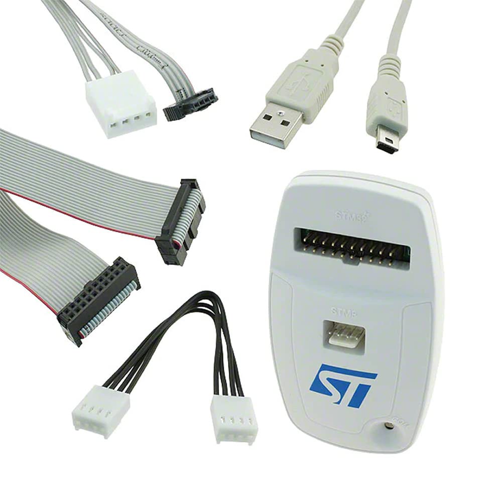
Figure 2: ST-Link/V2 device and its accompanying connection cables for different interfaces.
3.2. Software and Driver Installation
Drivers for the ST-LINK/V2 are typically included with the STMicroelectronics development tools. It is recommended to download the latest ST-LINK drivers and firmware from the official STMicroelectronics website.
- Visit the official STMicroelectronics website and navigate to the ST-LINK/V2 product page or the software and tools section.
- Download and install the latest ST-LINK drivers. These drivers are crucial for your operating system to recognize the device.
- Download and install the necessary integrated development environment (IDE) or programming software for your microcontroller family:
- For STM8 applications: ST Visual Develop (STVD) or ST Visual Program (STVP).
- For STM32 applications: Atollic TrueSTUDIO, IAR Embedded Workbench, Keil MDK-ARM, or TASKING.
- Ensure the ST-LINK/V2 firmware is up to date using the ST-LINK Utility software (usually part of the driver package).
4. Operating Instructions
Once the ST-LINK/V2 is connected and drivers are installed, you can begin programming and debugging your microcontrollers.
4.1. Programming and Debugging STM8
For STM8 microcontrollers, the ST-LINK/V2 uses the SWIM interface.
- Open ST Visual Develop (STVD) for debugging or ST Visual Program (STVP) for programming.
- In your chosen software, select ST-LINK as the programming/debugging tool.
- Configure the target microcontroller settings, including the SWIM interface speed (low-speed or high-speed) and application voltage.
- Load your firmware or project into the software.
- Initiate programming or debugging as required by the software interface. The status LED on the ST-LINK/V2 will blink during communication.
4.2. Programming and Debugging STM32
For STM32 microcontrollers, the ST-LINK/V2 uses the JTAG/SWD interface.
- Open your preferred IDE (e.g., Atollic TrueSTUDIO, IAR Embedded Workbench, Keil MDK-ARM, TASKING).
- In the IDE's project settings or debug configuration, select ST-LINK as the debugger/programmer.
- Ensure the correct interface (JTAG or SWD) is selected and verify the application voltage settings.
- Build your project and load the executable onto the target.
- Start the debugging session or program the flash memory. The status LED on the ST-LINK/V2 will blink during data transfer.

Figure 3: ST-Link/V2 in operation, showing the illuminated status LED indicating active communication.
4.3. Direct Firmware Update (DFU)
The ST-LINK/V2 supports Direct Firmware Update (DFU), allowing you to update its internal firmware. This is typically done via the ST-LINK Utility software and ensures compatibility with the latest microcontrollers and features. Refer to the ST-LINK Utility documentation for detailed DFU procedures.
5. Maintenance
To ensure the longevity and optimal performance of your ST-LINK/V2, follow these maintenance guidelines:
- Storage: Store the device in a dry, dust-free environment when not in use.
- Cleaning: Use a soft, dry cloth to clean the exterior of the device. Avoid using liquid cleaners or solvents.
- Handling: Handle the device and its cables with care. Avoid excessive bending or pulling of cables, especially near connectors.
- Temperature: Operate and store the device within its specified temperature range (0 to 50 °C).
- Firmware Updates: Regularly check for and apply firmware updates for the ST-LINK/V2 to ensure compatibility and access to new features.
6. Troubleshooting
If you encounter issues with your ST-LINK/V2, consider the following troubleshooting steps:
6.1. Device Not Recognized by PC
- USB Connection: Ensure the USB cable is securely connected to both the ST-LINK/V2 and the PC. Try a different USB port or cable.
- Drivers: Verify that the ST-LINK drivers are correctly installed. Reinstall them if necessary, downloading the latest version from STMicroelectronics.
- Other USB Devices: Disconnect other non-essential USB devices to rule out conflicts.
- PC Restart: Restart your computer.
6.2. Cannot Connect to Target Microcontroller
- Cable Connection: Ensure the SWIM or JTAG/SWD cable is correctly and securely connected to both the ST-LINK/V2 and the target board. Check for correct pin orientation.
- Target Power: Verify that the target microcontroller board is powered on and receiving the correct voltage.
- Voltage Compatibility: Confirm that the application voltage of your target board is within the supported range of the ST-LINK/V2 (1.65 V to 5.5 V for SWIM, 1.65 V to 3.6 V for JTAG/SWD).
- Interface Selection: In your IDE or programming software, ensure the correct interface (SWIM, JTAG, or SWD) is selected.
- Target Microcontroller State: The target microcontroller might be in a protected state (e.g., read-out protection). Refer to your microcontroller's datasheet for recovery procedures.
- Pinout Verification: Double-check the pinout of your target board's debug connector against the ST-LINK/V2 pinout.

Figure 4: JTAG/SWD 20-pin connector pinout diagram for reference.
6.3. Programming/Debugging Errors
- Firmware Version: Ensure your ST-LINK/V2 firmware is up to date.
- Software Version: Use the latest versions of your IDE and programming tools.
- Project Configuration: Verify that your project settings in the IDE match the target microcontroller and ST-LINK/V2 configuration.
- Power Supply: Ensure a stable power supply to both the ST-LINK/V2 and the target board.
7. Specifications
| Feature | Detail |
|---|---|
| Model Name | ST-LINK/V2 |
| Brand | STMicroelectronics |
| Product Dimensions | 4 x 3 x 1 inches |
| Item Weight | 0.01 Ounces |
| Power Supply | 5 V via USB connector |
| USB Interface | USB 2.0 full-speed compatible |
| SWIM Application Voltage | 1.65 V to 5.5 V |
| SWIM Programming Speed | 9.7 Kbytes/s (low), 12.8 Kbytes/s (high) |
| JTAG/SWD Application Voltage | 1.65 V to 3.6 V (5 V tolerant inputs) |
| Operating Temperature | 0 to 50 °C |
| Compatible Devices | Personal Computer |
| Connector Type | USB |
8. Warranty and Support
8.1. Warranty Information
Specific warranty terms for the ST-LINK/V2 are provided by the manufacturer, STMicroelectronics. Please refer to the official STMicroelectronics website or the documentation included with your purchase for detailed warranty information, including coverage period and conditions.
8.2. Technical Support
For technical assistance, driver updates, firmware updates, and additional resources, please visit the official STMicroelectronics support website. You can find comprehensive documentation, forums, and contact information for technical support there.
Manufacturer: STMicroelectronics
Website: www.st.com
Related documentsST-LINK/V2


Ask a question about this manual
Ask about setup, troubleshooting, compatibility, parts, safety, or missing instructions. Manuals+ will review the question and use this page’s manual context to help answer it.