1. Introduction
This manual provides essential instructions for the installation, operation, and maintenance of the EPEVER LS3024B PWM Solar Charge Controller. The LS3024B is designed for solar lighting systems, featuring 12V/24V auto-work capability, three-level intelligent PWM charging, and multiple load working modes. It ensures efficient and safe management of your solar power system.

Image 1.1: Front view of the EPEVER LS3024B PWM Solar Charge Controller.
2. Safety Instructions
- Ensure all wiring is correctly polarized. Incorrect wiring can damage the controller and other components.
- Connect the battery first, then the solar panel, and finally the load. Disconnect in the reverse order.
- Install the controller in a well-ventilated area, away from direct sunlight, high temperatures, and water.
- The controller is designed for indoor use. Protect it from moisture and dust.
- Do not disassemble or attempt to repair the controller. Contact qualified personnel for service.
- Ensure battery voltage is sufficient for the controller to recognize the battery type before installation.
- A fuse or circuit breaker should be installed on the battery side, close to the battery, with a rating not exceeding 1.25 times the rated current of the controller.
3. Product Overview
3.1 Key Features
- Automatic identification of 12V/24V system voltage.
- Three-level intelligent PWM charging: Equalize, Boost, and Float.
- Multiple load working modes: Manual control, Light ON/OFF, Light ON + Timer, and Time control.
- LED indicators for PV charging, battery status, and load status.
- Optional Remote Temperature Sensor (RTS) for accurate temperature compensation.
- RS485 communication port with standard MODBUS open architecture for real-time data monitoring and parameter setting via MT50, APP, or PC software.
- Utilizes MOSFET as an electronic switch for intelligent operation without mechanical switches.
- Software update function.
3.2 Components and Interfaces

Image 3.1: Front and bottom view of the controller with labeled components.
- Battery Status LED indicator: Shows battery charge level.
- Charging Status LED indicator: Indicates PV charging activity.
- Load Status LED indicator: Shows load output status.
- Switch Button: For manual control of the load.
- PV terminals: Connect to solar panel array.
- Battery terminals: Connect to battery bank.
- Load terminals: Connect to DC loads.
- Remote Temp Sensor: Port for optional temperature sensor.
- RJ45 communication port (COM): For connecting to MT50, PC, or APP via adapters.

Image 3.2: Top and bottom views of the controller, showing heat sink and ports.
4. Installation
Follow these steps for proper installation of the EPEVER LS3024B solar charge controller:
- Prepare Wiring: Ensure all wires are of appropriate gauge for the current and length, and that they are properly stripped.
- Mount the Controller: Mount the controller vertically on a wall or other stable surface in a well-ventilated area, ensuring adequate airflow around the heat sink.
- Connect the Battery: Connect the battery to the controller's battery terminals (marked with a battery symbol). Ensure correct polarity (+ to + and - to -). The battery indicator on the controller should turn green. If not, check the connection. This step must be performed first.
- Connect the Solar Panel: Connect the solar panel array to the controller's PV terminals (marked with a solar panel symbol). Ensure correct polarity.
- Connect the Load: Connect the DC load to the controller's load terminals (marked with a light bulb symbol). Ensure correct polarity.
- Install Fuse: A fuse should be installed on the battery positive line, as close to the battery as possible. The suggested distance is within 150mm.
- Optional: Remote Temperature Sensor: If using, connect the RTS to the designated port for accurate temperature compensation.
- Optional: Communication Cable: If using an MT50 remote meter, PC software, or mobile app, connect the appropriate communication cable (e.g., CC-USB-RS485-150U) to the RJ45 COM port.
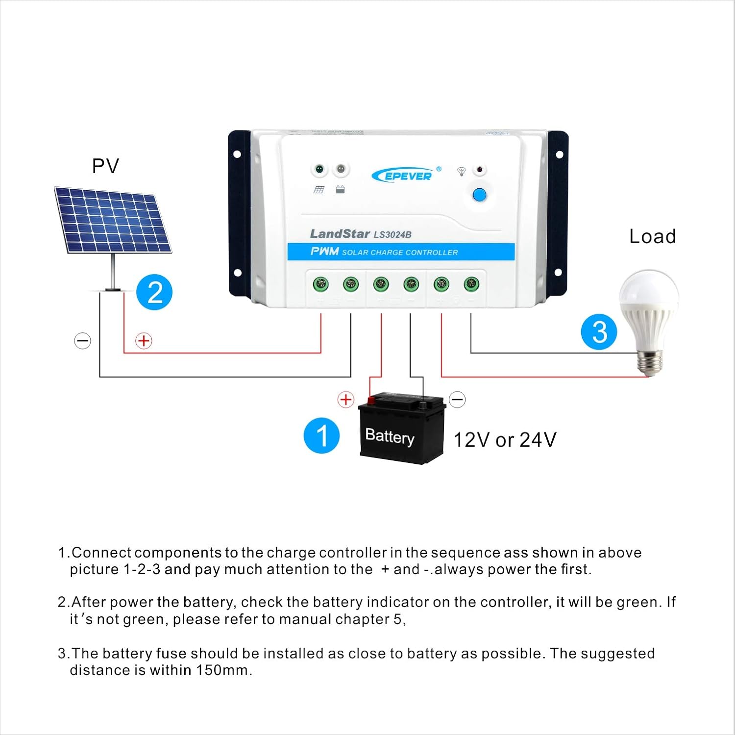
Image 4.1: Wiring diagram for the EPEVER LS3024B controller.
5. Operating Instructions
5.1 LED Indicators
- PV Charging LED: Indicates solar panel charging activity.
- Battery LED: Shows battery charge status (e.g., charging, full, low).
- Load LED: Indicates if the load output is active or inactive.
5.2 Load Working Modes
The controller supports various load working modes, which can typically be configured via the optional MT50 remote meter, PC software, or mobile application connected through the RS485 port.
- Manual Control: The load can be turned ON/OFF manually using the switch button on the controller or through the connected communication device.
- Light ON/OFF: The load automatically turns ON at dusk and OFF at dawn.
- Light ON + Timer: The load turns ON at dusk and stays ON for a set duration (e.g., 1-15 hours), then turns OFF.
- Time Control: The load operates during specific programmed time periods.
6. Electronic Protections
The EPEVER LS3024B controller incorporates comprehensive electronic protections to ensure system safety and longevity:
- PV Short Circuit Protection: Prevents damage from short-circuited solar panels.
- PV Reverse Polarity Protection: Protects against incorrect solar panel wiring.
- Battery Over Voltage Protection: Prevents battery overcharging.
- Battery Over Discharge Protection: Prevents deep discharge of the battery, extending its lifespan.
- Battery Reverse Polarity Protection: Protects against incorrect battery wiring.
- Load Short Circuit Protection: Protects the load and controller from short circuits.
- Load Overload Protection: Prevents damage from excessive load current.
- Controller Overheating Protection: Shuts down or reduces power if the controller temperature exceeds safe limits.
7. Technical Specifications

Image 7.1: Detailed technical specifications for LS1024B, LS2024B, and LS3024B models.
| Parameter | Value (LS3024B) |
|---|---|
| Nominal System Voltage | 12V/24V Auto Work |
| Rated Charge Current | 30A |
| Rated Discharge Current | 30A |
| Max. PV Voltage of Storage Battery | 34V |
| Battery Input Voltage Range | 8~32V |
| Equalize Charging Voltage* | Sealed: 14.6V, Flooded: 14.8V, User-defined: 9~17V |
| Boost Charging Voltage* | Gel: 14.2V, Sealed: 14.4V, Flooded: 14.6V, User-defined: 9~17V |
| Float Charging Voltage* | Gel/Sealed/Flooded: 13.8V, User-defined: 9~17V |
| Low Voltage Reconnect Voltage* | Sealed/Gel/Flooded: 12.6V, User-defined: 9~17V |
| Low Voltage Disconnect Voltage* | Sealed/Gel/Flooded: 11.1V, User-defined: 9~17V |
| Self-consumption | ≤8.4mA (12V); ≤7.8mA (24V) |
| Temperature Compensation Coefficient | -3mV/℃/2V (25℃) |
| Enclosure | IP30 |
| Grounding | Common Positive |
| Working Environment Temperature | -35℃ ~ 55℃ |
| Terminal | 8AWG (10mm²) |
| Dimensions (L×W×H) | 200 × 101.3 × 57 mm (7.87"L x 3.99"W x 2.24"H) |
| Net Weight | 0.5 kg |
*Technical data for 12V system at 25℃, twice in 24V system. Programmable voltage value by PC, MT50 and APP.

Image 7.2: Physical dimensions of the EPEVER LS3024B controller.
8. Troubleshooting
This section provides guidance for common issues. For more complex problems, contact technical support.
| Problem | Possible Cause | Solution |
|---|---|---|
| No display/Controller not powering on | Battery not connected or reverse polarity; Battery voltage too low. | Check battery connections and polarity. Ensure battery voltage is above the minimum operating voltage. |
| PV Charging LED off, but sun is present | Solar panel not connected or reverse polarity; PV voltage too low; PV short circuit. | Check solar panel connections and polarity. Ensure sufficient sunlight and PV voltage. Inspect for short circuits. |
| Load not working | Load not connected or reverse polarity; Load short circuit/overload; Battery low voltage disconnect; Load mode setting. | Check load connections and polarity. Verify load current. Check battery voltage. Adjust load working mode settings. |
| Battery not fully charging | Insufficient PV power; Incorrect battery type setting; High temperature. | Ensure adequate solar panel size and sunlight. Verify battery type setting. Ensure proper ventilation. |
9. Maintenance
Regular maintenance helps ensure the longevity and optimal performance of your solar charge controller:
- Check Connections: Periodically inspect all wiring connections for tightness and corrosion. Loose connections can cause voltage drops and overheating.
- Clean Controller: Keep the controller clean and free from dust and debris. Ensure the heat sink fins are not obstructed to allow for proper cooling.
- Inspect Wiring: Check all cables for signs of wear, damage, or insulation degradation. Replace damaged cables immediately.
- Battery Inspection: Regularly check battery terminals for corrosion and clean if necessary. Monitor battery voltage and health.
- Environment: Ensure the installation environment remains within the specified temperature and humidity ranges.
10. Optional Accessories
Enhance the functionality and monitoring capabilities of your LS3024B controller with these optional accessories:
- MT50 Remote Meter: Provides real-time data display, parameter setting, and load control.
- RTS300R47K3.81A Remote Temperature Sensor (3m): For accurate battery temperature compensation.
- CC-USB-RS485-150U PC Communication Cable (1.5m): Connects the controller to a PC for monitoring and parameter configuration.
- OTG-12CM OTG Cable (12cm): For connecting to mobile devices.


Image 10.1: Examples of optional accessories for the EPEVER LS3024B controller.
11. Support
For technical assistance, troubleshooting, or inquiries regarding your EPEVER LS3024B solar charge controller, please contact the authorized sales agent or EPEVER customer support. GolandCentury, an authorized sales agent for EPEVER, provides free technical support to customers.
For further information, refer to the official EPEVER website or contact your local distributor.


