1. Introduction
This manual provides essential information for the safe and effective use of the HiLetgo Mini 360 DC-DC Buck Converter Module. This compact module is designed to step down a higher DC input voltage to a lower, adjustable DC output voltage. It is suitable for various electronic projects, including RC applications, where a stable, regulated lower voltage is required from a higher voltage source.
2. Safety Information
Please read and understand the following safety precautions before operating the module:
- No Short Circuit Protection: This module does not include short circuit protection. Ensure that the output is not short-circuited, as this can damage the module and connected components.
- No Input Reverse Polarity Protection: The module does not have input reverse polarity protection. Connecting the input power with reversed polarity will damage the module. Always verify input polarity before connecting.
- Step-Down Only: This module is a buck converter, meaning it can only step down voltage. The output voltage must always be lower than the input voltage. It cannot be used to step up voltage.
- Current Limits: Adhere to the specified output current limits (Rated 1.8A, Max 3A for short durations). Exceeding these limits can lead to overheating and module failure.
- Proper Ventilation: Ensure adequate ventilation, especially when operating at higher currents, to prevent overheating.
- Insulation: Properly insulate all connections to prevent accidental short circuits.
- Professional Use: This product is intended for users with basic knowledge of electronics. If you are unsure about any aspect of its use, seek professional guidance.
3. Product Overview
3.1 Features
- Compact size, ideal for space-constrained applications.
- Non-isolated step-down (BUCK) module with synchronous rectification.
- Adjustable output voltage range from 1.0V to 17V.
- Wide input voltage range from 4.75V to 23V.
- High efficiency due to synchronous rectification.
3.2 Package Contents
Each package contains:
- 10 x HiLetgo Mini 360 DC-DC Step-down Adjustable Modules

Image 3.2.1: A pack of ten HiLetgo Mini 360 DC-DC Buck Converter Modules, showing their compact size and green PCB.

Image 3.2.2: Various packaging options for HiLetgo products, including sealed bags and a small cardboard box, all featuring the HiLetgo logo.
4. Specifications
| Parameter | Value |
|---|---|
| Module Properties | Non-isolated step-down module (BUCK) |
| Rectification | Synchronous rectification |
| Input Voltage | DC 4.75V - 23V |
| Output Voltage | DC 1.0V - 17V (Adjustable) |
| Output Current | Rated 1.8A (3A MAX, cannot be prolonged) |
| Output Ripple | 30mV (no-load) |
| Load Regulation | ±0.5% |
| Voltage Regulation | ±2.5% |
| Short Circuit Protection | No |
| Input Reverse Protection | No |
| Dimensions (L*W*H) | 17mm * 11mm * 4mm (approx. 0.67'' * 0.43'' * 0.16'') |
| Item Weight | 4.8 ounces (for 10 modules) |
| ASIN | B00LODGDYE |
| Item Model Number | 3-01-0105 |

Image 4.1: Top view of the Mini 360 module, showing its compact dimensions: approximately 17.9mm in length and 12mm in width.
5. Setup and Connections
Follow these steps to correctly set up your HiLetgo Mini 360 DC-DC Buck Converter Module:
- Identify Terminals: Locate the input and output terminals on the module. They are typically labeled "IN+" (Input Positive), "IN-" (Input Negative), "OUT+" (Output Positive), and "OUT-" (Output Negative).
- Input Power Connection: Connect your DC power source to the "IN+" and "IN-" terminals. Ensure the input voltage is within the specified range of 4.75V to 23V. Double-check polarity to avoid damage.
- Output Load Connection: Connect your load (e.g., LED, microcontroller, RC component) to the "OUT+" and "OUT-" terminals.
- Initial Voltage Adjustment (Crucial):
- Before connecting any load, connect a multimeter to the "OUT+" and "OUT-" terminals to monitor the output voltage.
- Apply input power.
- Using a small screwdriver, carefully turn the onboard potentiometer (the small screw-like component) to adjust the output voltage to your desired level. Turn clockwise to increase voltage, counter-clockwise to decrease.
- Once the desired output voltage is set, disconnect the input power, then connect your load.

Image 5.1: A detailed view of the Mini 360 module, highlighting the MP2307DN chip, inductor, and the small adjustable potentiometer for voltage regulation.
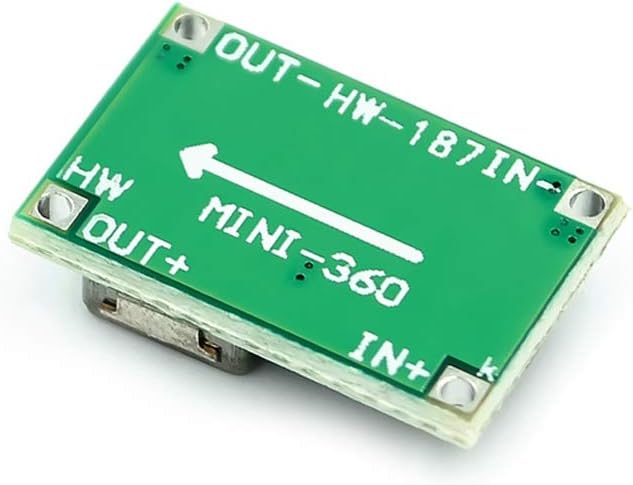
Image 5.2: The bottom side of the Mini 360 module, clearly showing the "IN+" and "IN-" input terminals, and "OUT+" and "OUT-" output terminals, along with the "MINI-360" model designation.
6. Operation
Once the module is correctly wired and the output voltage is set, operation is straightforward:
- Power On: Apply power to the input terminals. The module will convert the input voltage to the pre-set output voltage.
- Monitoring: It is recommended to periodically monitor the output voltage and current, especially during initial use or when changing loads, to ensure stable operation and prevent exceeding current limits.
- Voltage Adjustment: If the output voltage needs to be changed, disconnect the load, adjust the potentiometer as described in the Setup section, and then reconnect the load.
- Important Note: The output voltage will always be lower than the input voltage. For example, if your input is 5V, the maximum adjustable output will be slightly less than 5V.
7. Maintenance
The HiLetgo Mini 360 module requires minimal maintenance:
- Keep Clean: Keep the module free from dust, dirt, and moisture. Use a soft, dry brush or cloth for cleaning.
- Environmental Conditions: Operate the module within its specified temperature and humidity ranges. Avoid extreme conditions.
- Inspect Connections: Periodically check all wiring connections to ensure they are secure and free from corrosion or damage.
- Avoid Physical Stress: Do not apply excessive physical force or bend the PCB, as this can damage internal components.
8. Troubleshooting
If you encounter issues with your module, consider the following:
- No Output Voltage:
- Check input power supply: Ensure it is connected correctly and providing voltage within the 4.75V-23V range.
- Verify input polarity: Reversed input polarity will damage the module.
- Inspect connections: Ensure all wires are securely connected to the correct terminals.
- Potentiometer setting: The output voltage might be set too low. Try adjusting the potentiometer (without load) while monitoring with a multimeter.
- Output Voltage Not Adjustable / Difficult to Adjust:
- The potentiometer is very sensitive and small. Use a fine-tipped screwdriver and make very small adjustments.
- Ensure no load is connected during adjustment for accurate readings.
- If the potentiometer seems unresponsive or broken, the module may be faulty.
- Module Overheating:
- Check output current: Ensure the load current does not exceed the rated 1.8A (or 3A for short bursts).
- Verify input/output voltage difference: A large difference between input and output voltage, combined with high current, can increase heat dissipation.
- Ensure adequate ventilation around the module.
- Output Voltage is Higher Than Expected:
- Remember, this is a step-down converter. If the input voltage is very close to the desired output voltage, the module might not be able to regulate effectively. The output will always be slightly less than the input.
9. Warranty and Support
For technical support or if you encounter any issues with your HiLetgo product, please contact us:
- Email: support@hiletgo.com
- Website: www.hiletgo.com
- Amazon Store: Visit the HiLetgo Store on Amazon
Please provide your product model number (3-01-0105) and a detailed description of the issue when contacting support.


