1. Introduction
The Mastech MS2115A is a professional-grade digital clamp meter designed for accurate measurement of DC/AC current, DC/AC voltage, resistance, capacitance, frequency, and duty cycle. It features True RMS for AC measurements, a built-in Non-Contact Voltage (NCV) detector, diode check, continuity test, and a reading hold function. This manual provides essential information for safe and effective operation of your MS2115A clamp meter.
2. Safety Information
Please read and understand all safety information before operating this device. Failure to follow these instructions may result in electric shock, fire, or damage to the meter.
- Always ensure the meter is in the correct function mode before making measurements.
- Do not apply voltage or current that exceeds the maximum rated limits of the meter.
- Exercise extreme caution when working with live circuits. High voltages can be lethal.
- Inspect test leads for damage before each use. Do not use if insulation is compromised.
- Do not operate the meter if it appears damaged or if the case is open.
- Replace batteries immediately when the low battery indicator appears to ensure accurate readings.
- Adhere to local and national safety codes.
3. Product Features
The Mastech MS2115A clamp meter offers a range of advanced features for electrical testing:
- LCD with 5999 counts for precise readings.
- Jaw size up to ϕ40mm (1.6 inches) for large conductors.
- DC/AC current measurement up to 1000A.
- Tests AC/DC voltage, current, resistance, capacitance, frequency, and duty cycle.
- Built-in Non-Contact Voltage (NCV) detector for live wire detection without physical contact.
- True RMS for accurate AC voltage and AC current measurements of non-sinusoidal waveforms.
- Work light for illumination in dimly lit areas.
- Auto power off function to conserve battery life.
- Diode check and continuity test with audible buzzer.
- Reading hold function to freeze the displayed measurement.
4. Product Overview
Familiarize yourself with the components of your Mastech MS2115A clamp meter.

Figure 4.1: Front View of Mastech MS2115A Clamp Meter. This image displays the front of the Mastech MS2115A Digital Clamp Meter, highlighting its large LCD screen, rotary dial for function selection, clamp jaw, and input terminals. Key buttons such as RANGE, HZ%, MAX/MIN, REL, and HOLD are visible, along with the Mastech branding.
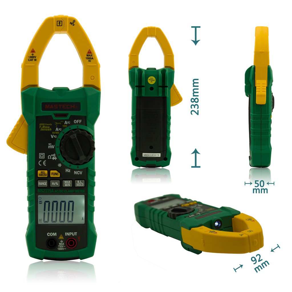
Figure 4.2: Mastech MS2115A Clamp Meter Dimensions. This image provides multiple views of the Mastech MS2115A, including front, back, side, and bottom angles, with measurements indicating its approximate height (238mm), width (92mm), and thickness (50mm). This helps users understand the physical size and form factor of the device.

Figure 4.3: Mastech MS2115A Clamp Meter Package Contents. This image shows the complete contents included with the Mastech MS2115A clamp meter. It features the clamp meter itself, a pair of red and black test leads, a carrying case, and a user manual. Please note that the 9V battery is typically not included and must be purchased separately.
5. Setup
5.1 Battery Installation
The Mastech MS2115A requires a 9V battery for operation. Please note that the battery is typically not included in the package and must be purchased separately.
- Ensure the meter is turned OFF.
- Locate the battery compartment cover on the back of the meter.
- Use a screwdriver to loosen the screw(s) securing the battery cover.
- Remove the battery cover.
- Connect a new 9V battery to the battery clips, observing correct polarity.
- Place the battery into the compartment.
- Replace the battery cover and secure it with the screw(s).
6. Operating Instructions
6.1 Power On/Off
To power on the meter, rotate the function dial from the OFF position to any desired measurement function. To power off, rotate the dial back to the OFF position. The meter features an auto power-off function to conserve battery life after a period of inactivity.
6.2 Function Selection
Use the central rotary dial to select the desired measurement function (e.g., V∼, V−, A∼, A−, Ω, Diode/Continuity, CAP, Hz%). Some positions may have multiple functions; press the FUNC button to cycle through them.
6.3 Measuring AC/DC Current (Clamp Jaw)
- Rotate the dial to the A∼ (AC Current) or A− (DC Current) position.
- Press the jaw trigger to open the clamp jaw.
- Encircle only one conductor with the clamp jaw. Ensure the jaw is fully closed.
- Read the current value on the LCD. For DC current, observe the polarity indicator.
6.4 Measuring AC/DC Voltage
- Insert the red test lead into the INPUT terminal and the black test lead into the COM terminal.
- Rotate the dial to the V∼ (AC Voltage) or V− (DC Voltage) position.
- Connect the test leads in parallel to the circuit or component under test.
- Read the voltage value on the LCD. For DC voltage, observe the polarity indicator.
6.5 Measuring Resistance (Ω)
- Insert the red test lead into the INPUT terminal and the black test lead into the COM terminal.
- Rotate the dial to the Ω (Resistance) position.
- Ensure the circuit or component is de-energized before connecting the test leads.
- Connect the test leads across the component to measure its resistance.
- Read the resistance value on the LCD.
6.6 Measuring Capacitance (CAP)
- Insert the red test lead into the INPUT terminal and the black test lead into the COM terminal.
- Rotate the dial to the CAP (Capacitance) position.
- Ensure the capacitor is fully discharged before connecting the test leads.
- Connect the test leads across the capacitor.
- Read the capacitance value on the LCD.
6.7 Diode Check and Continuity Test
- Insert the red test lead into the INPUT terminal and the black test lead into the COM terminal.
- Rotate the dial to the Diode/Continuity position. Press FUNC to switch between diode and continuity modes if necessary.
- For Diode Check: Connect the red lead to the anode and the black lead to the cathode of the diode. The forward voltage drop will be displayed. Reverse the leads to check for open circuit.
- For Continuity Test: Connect the test leads across the circuit or component. An audible beep indicates continuity (low resistance).
6.8 Non-Contact Voltage (NCV) Detection
- Rotate the dial to the NCV position.
- Move the top front part of the meter (near the clamp jaw) close to the conductor or outlet you wish to test.
- The meter will indicate the presence of AC voltage through an audible beep and/or visual indicator on the LCD.
6.9 Special Functions (RANGE, HZ%, MAX/MIN, REL, HOLD)
- RANGE: Press to switch between auto-ranging and manual ranging. In manual mode, press repeatedly to cycle through ranges.
- HZ%: Press to measure frequency (Hz) or duty cycle (%) in relevant voltage/current modes.
- MAX/MIN: Press to record the maximum and minimum readings during a measurement session.
- REL (Relative Measurement): Press to store the current reading as a reference value. Subsequent measurements will be displayed as the difference from this reference.
- HOLD: Press to freeze the current reading on the display. Press again to release.
7. Maintenance
7.1 Cleaning
To clean the meter, wipe the case with a damp cloth and a mild detergent. Do not use abrasives or solvents. Ensure the meter is powered off and disconnected from any circuits before cleaning.
7.2 Battery Replacement
When the low battery indicator appears on the LCD, replace the 9V battery as described in Section 5.1. Prompt battery replacement ensures continued accuracy and proper operation.
8. Troubleshooting
If you encounter issues with your MS2115A, refer to the following common problems and solutions:
- No Display: Check if the meter is powered on. Ensure the battery is correctly installed and has sufficient charge. Replace the battery if necessary.
- Incorrect Readings: Verify that the function dial is set to the correct measurement mode. Ensure test leads are properly connected and not damaged. For current measurements, ensure only one conductor is within the clamp jaw. Check battery level.
- No Continuity Beep: Ensure the meter is in continuity mode. Check if the circuit has very high resistance or is open.
- NCV Not Detecting: Ensure the meter is in NCV mode. The NCV function detects AC voltage; it will not detect DC voltage. Ensure the sensor area is close enough to the live conductor.
If problems persist, contact Mastech customer support for further assistance.
9. Specifications
The following table outlines the general specifications for the Mastech MS2115A Digital Clamp Meter:
| Specification | Value |
|---|---|
| Brand | Mastech |
| Model Number | MS2115A |
| Measurement Type | Ammeter (Clamp Meter) |
| Style | Digital |
| Power Source | Battery Powered (9V) |
| Display | LCD, 5999 counts |
| Jaw Size | Up to ϕ40mm (1.6 inches) |
| AC/DC Current | Up to 1000A |
| True RMS | For AC Voltage and AC Current |
| Package Dimensions | 10.63 x 5.83 x 2.36 inches |
| Item Weight | 1.41 Pounds |
10. Warranty and Support
The Mastech MS2115A Digital DC/AC Clamp Meter is manufactured by Mastech. For warranty information, technical support, or service inquiries, please refer to the official Mastech website or contact their customer service department. Keep your purchase receipt as proof of purchase for any warranty claims.


