
Flysky FS-GT2
Flysky FS-GT2 RC Transmitter and FS-GR3E Receiver User Manual
Model: FS-GT2 | Brand: Flysky
Introduction
This manual provides comprehensive instructions for the safe and effective operation of your Flysky FS-GT2 2.4GHz 2-Channel Digital Radio Controller and FS-GR3E Receiver. This system is designed for use with RC cars and boats, offering reliable control and advanced features. Please read this manual thoroughly before use to ensure proper setup and to maximize the performance and longevity of your equipment.

Image: The Flysky FS-GT2 RC Transmitter and FS-GR3E Receiver, showcasing the complete radio system.
Safety Information
- Always operate your RC vehicle in a safe and responsible manner.
- Ensure batteries are correctly installed and charged before each use.
- Do not operate the system near other radio equipment or in areas with strong electromagnetic interference.
- Keep the transmitter and receiver away from water, moisture, and extreme temperatures.
- This product is recommended for users aged 14 years and up. Adult supervision is advised for younger users.
- Disconnect batteries from both transmitter and receiver when not in use.
Product Overview and Components
FS-GT2 Transmitter
The FS-GT2 is a 2-channel pistol-grip transmitter designed for intuitive control of RC vehicles. Below are the key components and their functions.

Image: Front view diagram of the FS-GT2 transmitter, labeling the Control Box, 2.4G Antenna, Steering Wheel, Throttle Trigger, and Battery Box.
- 1. Control Box: Houses internal electronics and adjustment dials.
- 2. 2.4G Antenna: Transmits the radio signal to the receiver.
- 3. Steering Wheel: Controls the steering of the RC vehicle.
- 4. Throttle Trigger: Controls the forward/reverse and braking of the RC vehicle.
- 5. Battery Box: Compartment for the transmitter's power source.

Image: Side and back view diagram of the FS-GT2 transmitter, labeling various controls and ports.
- 6. ST REV (Steering Reverse): Reverses the steering channel direction.
- 7. POWER LED: Indicates power status.
- 8. ST TRIM (Steering Trim): Adjusts the neutral position of the steering.
- 9. POWER SW (Power Switch): Turns the transmitter on/off.
- A. TH REV (Throttle Reverse): Reverses the throttle channel direction.
- B. POWER CHECK: Button to check battery level.
- C. BIND: Button used for binding the transmitter to the receiver.
- D. D/R (Dual Rate): Adjusts the maximum steering angle.
- E. TH TRIM (Throttle Trim): Adjusts the neutral position of the throttle.
- F. CHARGER: Port for connecting a charger (if using rechargeable batteries).
- G. DSC FOR SIMULATE: Port for connecting to a simulator.
FS-GR3E Receiver
The FS-GR3E is a 3-channel receiver that pairs with the FS-GT2 transmitter, providing reliable signal reception for your RC vehicle.

Image: The Flysky FS-GR3E 3-channel receiver, showing its compact size and port layout.
The receiver features multiple ports for connecting servos (steering, throttle) and other accessories, along with a bind port for pairing with the transmitter.
Setup
1. Transmitter Battery Installation
The FS-GT2 transmitter requires 8 AA batteries (not included) for operation. Ensure you use fresh, high-quality batteries.
- Locate the battery compartment on the bottom of the transmitter.
- Slide the battery cover open.
- Insert 8 AA batteries, paying close attention to the correct polarity (+/-) as indicated inside the compartment.
- Close the battery cover securely.

Image: The open battery compartment of the FS-GT2 transmitter, showing where to insert the 8 AA batteries.
2. Receiver Connection
Connect the receiver to your RC vehicle's electronic speed controller (ESC) and steering servo.
- Connect the ESC's throttle cable to Channel 2 (CH2) on the receiver.
- Connect the steering servo's cable to Channel 1 (CH1) on the receiver.
- If your ESC does not provide power to the receiver, connect a separate battery pack to the B/C port (Battery/Bind) on the receiver. Ensure correct polarity.
3. Binding the Transmitter and Receiver
Binding is the process of linking the transmitter and receiver so they communicate exclusively with each other.
- Ensure the transmitter is turned OFF and the receiver is connected to power (via ESC or separate battery).
- Insert the bind plug (included with the receiver) into the B/C (Battery/Bind) port on the receiver. The receiver's LED should start flashing rapidly.
- While holding down the BIND button on the transmitter (located under the protective cover), turn the transmitter ON.
- The receiver's LED should turn solid, indicating a successful bind.
- Release the BIND button on the transmitter.
- Turn off both the transmitter and receiver.
- Remove the bind plug from the receiver. Store it safely for future use.
- Turn on the transmitter first, then the receiver. The receiver's LED should be solid, confirming the connection.
Note: If the binding process fails, repeat the steps carefully. Ensure no other 2.4GHz devices are interfering during binding.
Operating Instructions
Basic Operation
- Power On: Always turn on the transmitter first, then the receiver.
- Steering: Rotate the steering wheel left or right to control the direction of your vehicle.
- Throttle: Pull the throttle trigger towards you for forward movement. Push it away from you for reverse and braking.
- Power Off: Always turn off the receiver first, then the transmitter.
Adjustments
- ST TRIM (Steering Trim): Use this dial to fine-tune the steering neutral position. If your vehicle pulls to one side when the steering wheel is centered, adjust the ST TRIM until it drives straight.
- TH TRIM (Throttle Trim): Adjust this dial to set the throttle neutral position. If your vehicle creeps forward or backward when the throttle trigger is released, adjust the TH TRIM until it remains stationary.
- ST REV (Steering Reverse): This switch reverses the direction of the steering channel. If your vehicle steers right when you turn the wheel left, flip this switch.
- TH REV (Throttle Reverse): This switch reverses the direction of the throttle channel. If your vehicle goes reverse when you pull the trigger for forward, flip this switch.
- D/R (Dual Rate): This dial adjusts the maximum steering angle. Turning it down will reduce the sensitivity and maximum turning radius, which can be useful for beginners or for driving in tight spaces. Turning it up increases the steering throw.
Maintenance
- Cleaning: Use a soft, dry cloth to clean the transmitter and receiver. Avoid using solvents or harsh chemicals.
- Storage: Store the system in a cool, dry place away from direct sunlight and extreme temperatures. Remove batteries from the transmitter if storing for extended periods.
- Battery Care: Replace AA batteries in the transmitter when the low voltage warning activates (under 9V). If using rechargeable batteries, ensure they are charged with a compatible charger connected to the transmitter's charge port.
- Antenna Care: Do not bend or excessively stress the transmitter's antenna. Ensure the receiver's antenna is properly routed and protected within the vehicle.
Troubleshooting
| Problem | Possible Cause | Solution |
|---|---|---|
| No power to transmitter | Dead or incorrectly installed batteries | Check battery polarity; replace with fresh AA batteries. |
| No control of vehicle | Not bound; receiver not powered; loose connections | Perform binding procedure; check receiver power supply; ensure all cables are securely connected. |
| Vehicle steers in wrong direction | Steering channel reversed | Flip the ST REV switch on the transmitter. |
| Vehicle moves in wrong direction (throttle) | Throttle channel reversed | Flip the TH REV switch on the transmitter. |
| Vehicle drifts or doesn't stop at neutral | Trim settings incorrect | Adjust ST TRIM or TH TRIM dials until the vehicle remains straight/stationary. |
| Short range or intermittent signal | Low transmitter battery; interference; damaged antenna | Replace transmitter batteries; avoid operating near other radio sources; check transmitter and receiver antennas for damage. |
Specifications
FS-GT2 Transmitter Specifications
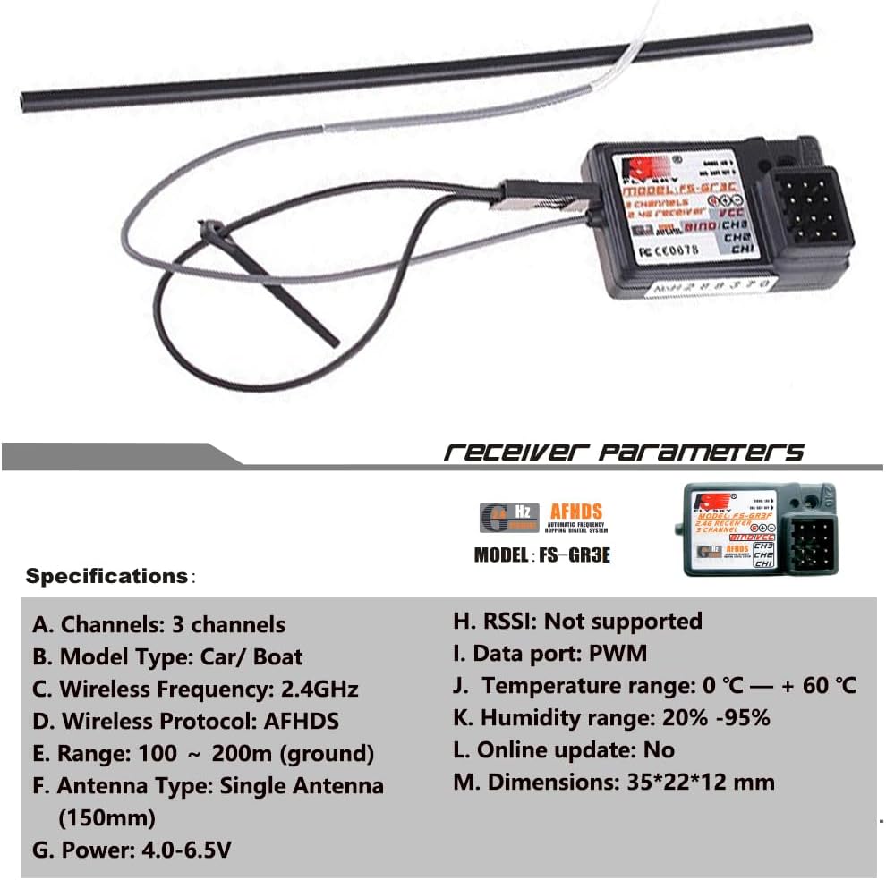
Image: Diagram detailing the technical specifications of the Flysky FS-GT2 transmitter.
| Feature | Detail |
|---|---|
| Channels | 2 Channels |
| Model Type | Car / Boat |
| RF Power | Less than 20dbm |
| Modulation | GFSK |
| Code Type | Digital |
| Sensitivity | 1024 |
| Low Voltage Warning | Yes (under 9V) |
| DSC Port | 3.5mm |
| Charger Port | Yes |
| Power | 12V DC (8 AA batteries) |
| Weight | 328g |
| Antenna Length | 26mm |
| Dimensions (L x W x H) | 159mm x 99mm x 315mm |
| Color | Black + Orange |
| Certificate | CE FCC |
FS-GR3E Receiver Specifications

Image: Diagram detailing the technical specifications of the Flysky FS-GR3E receiver.
| Feature | Detail |
|---|---|
| Channels | 3 Channels |
| Model Type | Car / Boat |
| Wireless Frequency | 2.4GHz |
| Wireless Protocol | AFHDS |
| Range | 100 ~ 200m (ground) |
| Antenna Type | Single Antenna (150mm) |
| Power | 4.0-6.5V |
| RSSI | Not supported |
| Data Port | PWM |
| Temperature Range | 0°C ~ +60°C |
| Humidity Range | 20% - 95% |
| Online Update | No |
| Dimensions | 35mm x 22mm x 12mm |
Warranty and Support
For warranty information and technical support, please refer to the official Flysky website or contact your local distributor. Keep your purchase receipt as proof of purchase for any warranty claims.
For further assistance or inquiries, please visit the Flysky Store on Amazon.
Related documentsFS-GT2


Ask a question about this manual
Ask about setup, troubleshooting, compatibility, parts, safety, or missing instructions. Manuals+ will review the question and use this page’s manual context to help answer it.