1. Introduction
This manual provides essential information for the safe and effective installation, operation, and maintenance of the Honeywell L4064B2210 Furnace Fan Limit Switch. This component is designed as an OEM replacement part for compatible Honeywell furnaces. Please read these instructions thoroughly before proceeding with any installation or service.
2. Safety Information
WARNING: Improper installation, adjustment, alteration, service, or maintenance can cause property damage, injury, or death. Read these instructions thoroughly before installing or servicing this equipment.
- Always disconnect power to the furnace at the main service panel before installing or servicing the fan limit switch. Failure to do so can result in electrical shock or severe injury.
- Installation and servicing should only be performed by a qualified heating and air conditioning technician.
- Ensure all wiring connections are secure and comply with local electrical codes.
- Do not bypass or tamper with safety devices.
- Wear appropriate personal protective equipment (PPE) during installation and service.
3. Product Overview
The Honeywell L4064B2210 is a combination fan and limit control switch designed for use in forced air furnaces. Its primary functions are:
- Fan Control: Automatically turns the furnace blower fan on and off based on plenum temperature, ensuring efficient heat distribution.
- High Limit Control: Acts as a safety device, shutting down the furnace burner if the plenum temperature exceeds a preset safe limit, preventing overheating.
This specific model is an 11-inch switch, designed for direct OEM replacement in compatible Honeywell furnace systems.
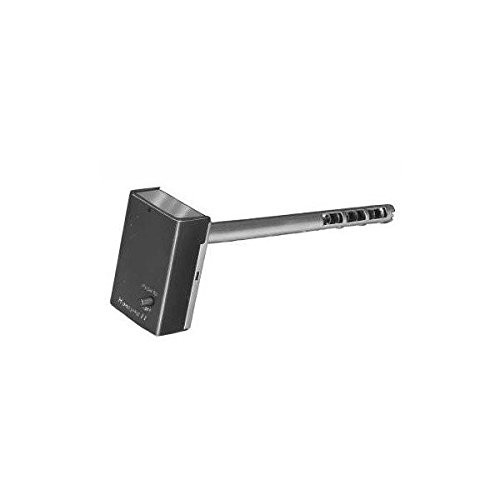
Figure 1: Honeywell L4064B2210 Furnace Fan Limit Switch. This image shows the general appearance of the combination fan and limit switch, featuring its housing and terminal connections.
4. Installation and Setup
Professional installation by a qualified technician is strongly recommended for this component.
- Power Disconnection: Before beginning any work, turn off all electrical power to the furnace at the main circuit breaker or fuse box. Verify power is off using a voltage tester.
- Access: Locate the existing fan limit switch on the furnace plenum. This is typically a rectangular box with a long probe extending into the furnace.
- Wiring Disconnection: Carefully label and disconnect all wires from the old fan limit switch terminals. Take a photograph of the wiring configuration for reference.
- Removal of Old Switch: Remove the mounting screws or clips securing the old switch to the furnace. Gently pull the switch and its probe out of the plenum.
- Mounting New Switch: Insert the probe of the new Honeywell L4064B2210 switch into the plenum opening. Ensure the switch housing is flush against the furnace and secure it with the appropriate mounting screws or clips. This is a panel mount type switch.
- Wiring Connection: Reconnect the wires to the new switch's screw terminals according to the labels or photograph taken earlier. Ensure all connections are tight and secure. The switch features Normally Open contacts and operates in a parallel circuit configuration.
- Temperature Settings: Adjust the fan ON, fan OFF, and high limit temperature settings on the new switch to match the manufacturer's specifications for your furnace model. The typical operating range is between 100°F and 200°F.
- Power Restoration and Testing: Restore power to the furnace. Initiate a heating cycle and observe the furnace operation. Verify that the fan turns on and off at the correct temperatures and that the high limit safety functions properly.
5. Operation
The Honeywell L4064B2210 operates automatically to manage your furnace's fan and ensure safe temperature limits. It also offers manual control capabilities.
- Automatic Fan Operation: When the furnace burner ignites, the plenum temperature rises. Once the temperature reaches the set 'Fan ON' point, the fan limit switch activates the blower fan to distribute heated air. As the burner cycles off and the plenum cools, the fan continues to run until the temperature drops to the set 'Fan OFF' point, at which time the fan deactivates.
- High Limit Safety: If, for any reason, the plenum temperature exceeds the 'High Limit' setting, the switch will automatically shut off the furnace burner to prevent dangerous overheating. The burner will remain off until the temperature drops to a safe level, at which point the switch will reset.
- Manual Fan Control: Many fan limit switches include a manual fan override lever or button. This allows the user to turn the blower fan on continuously, independent of the furnace's heating cycle. This can be useful for circulating air or for specific diagnostic purposes. Refer to your furnace's specific documentation for details on manual control.
6. Maintenance
The Honeywell L4064B2210 fan limit switch is a robust component designed for long-term reliability. Regular, simple maintenance can help ensure its continued proper function.
- Annual Inspection: It is recommended to have a qualified technician inspect the fan limit switch annually as part of routine furnace maintenance.
- Cleaning: With power disconnected, visually inspect the switch and its probe for any accumulation of dust, dirt, or debris. Gently clean the exterior of the switch and the exposed portion of the probe with a soft, dry brush or cloth. Do not use liquids or abrasive cleaners.
- Wiring Check: During inspection, ensure all wiring connections to the screw terminals are still tight and free from corrosion.
- No User-Serviceable Internal Parts: The internal components of the fan limit switch are not user-serviceable. If the switch is malfunctioning, it should be replaced by a qualified technician.
7. Troubleshooting
If your furnace is experiencing issues related to fan operation or overheating, the fan limit switch may be a contributing factor. Always ensure power is disconnected before inspecting components.
- Fan Not Turning On:
- Check if the furnace is actually heating. If not, the issue may be with the thermostat or burner.
- Verify the 'Fan ON' temperature setting on the switch is appropriate.
- Inspect wiring connections for looseness or corrosion.
- Ensure the fan motor is operational.
- Fan Not Turning Off:
- Check the 'Fan OFF' temperature setting.
- Ensure the furnace plenum is cooling down properly after the burner cycles off.
- If the manual fan override is engaged, disengage it.
- Furnace Overheating / High Limit Tripping:
- Verify the 'High Limit' temperature setting is correct for your furnace.
- Check for restricted airflow (e.g., dirty air filter, blocked vents).
- Ensure the furnace burner is not over-firing.
- The high limit switch may be faulty and require replacement.
- No Furnace Operation:
- Check main power supply to the furnace.
- Ensure the thermostat is calling for heat.
- A tripped high limit switch can prevent burner ignition.
For persistent or complex issues, contact a qualified HVAC technician. Do not attempt repairs beyond basic inspection if you are not trained to do so.
8. Specifications
| Specification | Detail |
|---|---|
| Model Number | L4064B2210 |
| Brand | Honeywell |
| Switch Type | Combination Fan & Limit Switch |
| Operation Mode | Automatic (Manual override possible) |
| Contact Type | Normally Open |
| Connector Type | Screw |
| Terminal Type | Screw |
| Circuit Type | Parallel |
| Actuator Type | Push Button (for manual control, if present) |
| Contact Material | Copper |
| International Protection Rating | IP00 |
| Number of Positions | 1 |
| Lower Temperature Rating | 100 Degrees Fahrenheit |
| Upper Temperature Rating | 200 Degrees Fahrenheit |
| Mounting Type | Panel Mount |
| Compatible Devices | Honeywell furnaces |
| Product Dimensions (L x W x H) | 6 x 6 x 6 inches (Note: 11-inch probe length) |
| Item Weight | 1.25 pounds |
| UPC | 789957517884 |
9. Warranty and Support
Specific warranty information for the Honeywell L4064B2210 OEM Furnace Fan Limit Switch may vary depending on the retailer and date of purchase. Please retain your proof of purchase for any warranty claims.
- For detailed warranty terms, refer to the documentation provided at the time of purchase or contact the seller directly.
- For technical support or assistance with installation and troubleshooting, it is recommended to contact a qualified HVAC professional or the official Honeywell customer support channels.
- You can often find additional support resources and contact information on the official Honeywell website or brand store.


