
EX ELECTRONIX EXPRESS 01AMA7050
Analog Multimeter User Manual
Model: 01AMA7050 | Brand: EX ELECTRONIX EXPRESS
1. Introduction
This manual provides detailed instructions for the safe and effective use of your EX ELECTRONIX EXPRESS Analog Multimeter, Model 01AMA7050. This general-purpose multimeter offers 7 functions and 20 ranges for various electrical measurements, including DC Voltage, AC Voltage, DC Current, Resistance, and Battery Test. Please read this manual thoroughly before operation.

Figure 1.1: Package Contents - Analog Multimeter, Test Leads, and User Manual.
2. Safety Information
Always observe standard safety precautions when using this multimeter. Failure to do so may result in injury or damage to the meter or equipment under test.
- Do not apply voltage or current to the meter that exceeds the specified maximum limits.
- Ensure the test leads are in good condition, without cracks or damaged insulation.
- Always disconnect power to the circuit before measuring resistance or continuity.
- Be cautious when working with live circuits. Use appropriate personal protective equipment.
- The meter is rated for CAT II 600V. Do not use it for measurements exceeding this category or voltage.
- Replace batteries promptly when the low battery indicator appears to ensure accurate readings.
3. Product Overview
The Analog Multimeter 01AMA7050 features a clear analog display, a rotary function switch, and multiple input jacks for versatile measurements.

Figure 3.1: Analog Multimeter with Test Leads.
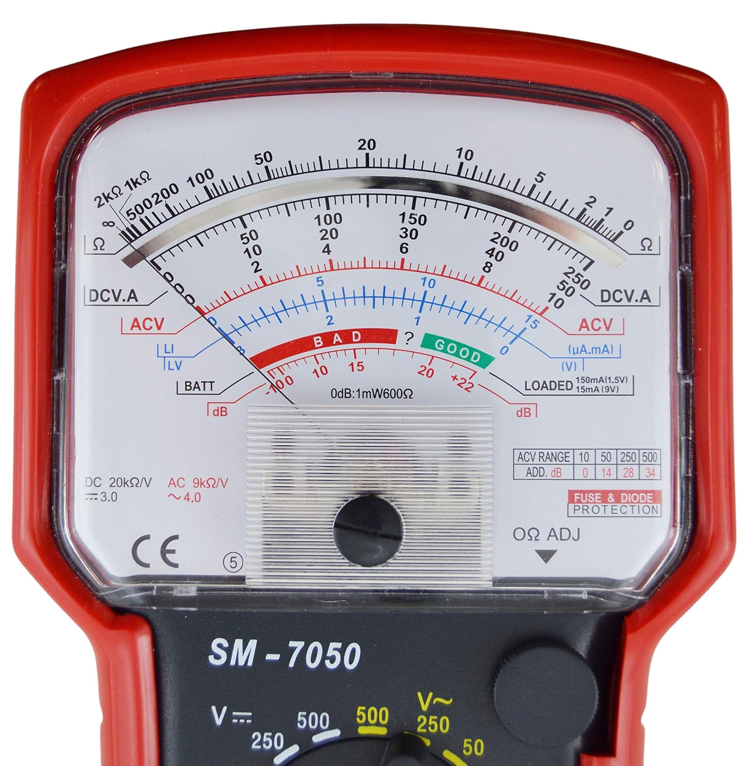
Figure 3.2: Multimeter Analog Display and Controls.
Key Components:
- Analog Display: Features multiple scales for DCV, ACV, DCA, Resistance, and dB.
- Rotary Switch: Selects the desired measurement function and range.
- Input Jacks:
- COM (Common): For the black (negative) test lead.
- VΩmA: For the red (positive) test lead for voltage, resistance, and milliampere current measurements.
- 10A: For the red (positive) test lead for high current (up to 10A) measurements.
- Ω ADJ (Ohm Adjustment): Knob for zeroing the meter before resistance measurements.
- Test Leads: Red (positive) and Black (negative) leads with probes.
- Protective Holster: A removable red holster provides protection for the meter.

Figure 3.3: Multimeter with Detached Protective Holster.
4. Setup
4.1 Battery Installation
The multimeter requires one 9V battery and two 1.5V AA batteries for operation. These are typically located in a compartment on the back of the meter.
- Locate the battery compartment cover on the back of the meter.
- Remove the screw(s) securing the cover and lift it off.
- Insert the 9V battery and two 1.5V AA batteries, observing correct polarity (+/-).
- Replace the battery compartment cover and secure it with the screw(s).
4.2 Connecting Test Leads
Connect the test leads to the appropriate input jacks on the multimeter.
- Insert the black test lead into the COM (Common) jack.
- For most measurements (voltage, resistance, low current), insert the red test lead into the VΩmA jack.
- For high current measurements (up to 10A), insert the red test lead into the 10A jack.

Figure 4.1: Multimeter with Detached Test Leads.
5. Operating Instructions
5.1 General Measurement Principles
Analog multimeters display readings using a needle on a graduated scale. It is crucial to select the correct scale for the chosen function and range. Always start with a higher range if the approximate value is unknown to prevent damage to the meter.
5.2 DC Voltage Measurement (DCV)
Ranges: 0.1V, 2.5V, 25V, 250V, 500V
- Connect the red test lead to the VΩmA jack and the black test lead to the COM jack.
- Set the rotary switch to the desired DCV range. If unsure, start with the highest range (500V).
- Connect the test probes in parallel across the component or circuit to be measured, observing polarity (red to positive, black to negative).
- Read the value on the appropriate DCV scale on the analog display.
5.3 AC Voltage Measurement (ACV)
Ranges: 10V, 50V, 250V, 500V
- Connect the red test lead to the VΩmA jack and the black test lead to the COM jack.
- Set the rotary switch to the desired ACV range. If unsure, start with the highest range (500V).
- Connect the test probes in parallel across the AC voltage source or component. Polarity is not critical for AC measurements.
- Read the value on the appropriate ACV scale on the analog display.
5.4 DC Current Measurement (DCA)
Ranges: 50uA, 5mA, 50mA, 500mA, 10A
- Important: Current measurements require the meter to be connected in series with the circuit. Disconnect power before connecting the meter.
- For ranges up to 500mA, connect the red test lead to the VΩmA jack. For 10A measurements, connect the red test lead to the 10A jack. Connect the black test lead to the COM jack.
- Set the rotary switch to the desired DCA range. Start with the highest range if the current is unknown.
- Break the circuit and connect the multimeter in series, observing polarity.
- Apply power to the circuit and read the value on the appropriate DCA scale.
5.5 Resistance Measurement (Ω)
Ranges: 2kΩ, 20kΩ, 200kΩ, 2MΩ, 20MΩ
- Connect the red test lead to the VΩmA jack and the black test lead to the COM jack.
- Set the rotary switch to the desired Resistance (Ω) range.
- Zero Adjustment: Short the red and black test probes together. Adjust the Ω ADJ knob until the needle points exactly to '0' on the Ohm scale. This step is crucial for accurate resistance readings.
- Disconnect power from the component to be measured. Connect the test probes across the component.
- Read the value on the Ohm scale. Note that the Ohm scale reads from right to left (0 to infinity).
5.6 Battery Test (BATT)
Ranges: 1.5V, 9V
- Connect the red test lead to the VΩmA jack and the black test lead to the COM jack.
- Set the rotary switch to the 1.5V BATT or 9V BATT range, corresponding to the battery you wish to test.
- Connect the test probes across the battery terminals, observing polarity (red to positive, black to negative).
- Read the battery condition on the 'GOOD' / 'BAD' scale.
6. Maintenance
6.1 Cleaning
Wipe the meter with a damp cloth and mild detergent. Do not use abrasives or solvents. Ensure the meter is dry before use.
6.2 Battery Replacement
Replace batteries as described in Section 4.1 when the meter's performance degrades or the low battery indicator (if present) activates.
6.3 Fuse Replacement
The meter is fused for protection. If the current measurement function stops working, the fuse may need replacement. Refer to the meter's internal markings for fuse specifications. Always replace with a fuse of the same type and rating.
6.4 Storage
When not in use for extended periods, remove the batteries to prevent leakage. Store the meter in a cool, dry place, away from direct sunlight and extreme temperatures.
7. Troubleshooting
- No Reading / Needle Not Moving:
- Check battery condition and ensure they are installed correctly.
- Verify test leads are properly connected to the meter and the circuit.
- Ensure the rotary switch is set to the correct function and range.
- For resistance measurements, ensure the meter is zeroed (Ω ADJ).
- Check the fuse if current measurement is not working.
- Inaccurate Reading:
- Ensure the correct scale is being read for the selected range.
- Verify the meter is zeroed for resistance measurements.
- Check battery voltage; low batteries can affect accuracy.
- Ensure good contact between probes and the circuit.
8. Specifications
Accuracy is indicated as ±[% of reading]. It is referred to the following reference conditions: 23°C ± 5°C with RH<75%.
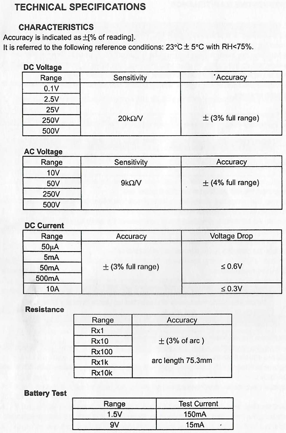
Figure 8.1: Technical Specifications Table.
| Characteristic | Value |
|---|---|
| Model Number | 01AMA7050 |
| Functions | 7 |
| Ranges | 20 |
| Power Source | Battery Powered (9V and 1.5V) |
| Style | Classic |
| Color | Red (Holster color may vary) |
| Min. Operating Voltage | 0.1 Volts |
| Function | Range | Sensitivity / Accuracy |
|---|---|---|
| DC Voltage | 0.1V | 20kΩ/V, ±3% f.s. |
| 2.5V | ||
| 25V | ||
| 250V | ||
| 500V | ||
| AC Voltage | 10V | 9kΩ/V, ±4% f.s. |
| 50V | ||
| 250V | ||
| 500V | ||
| DC Current | 50uA | ±3% f.s. |
| 5mA | ||
| 50mA | ||
| 500mA | ||
| 10A | ||
| Resistance | Rx1 | ±3% of arc (Arc length: 75.3mm) |
| Rx10 | ||
| Rx100 | ||
| Rx1K | ||
| Rx10K | ||
| Battery Test | 1.5V | Test Current: 150mA |
| 9V | Test Current: 15mA |
9. Warranty and Support
For warranty information or technical support, please contact EX ELECTRONIX EXPRESS directly through their official website or the retailer from whom the product was purchased. Keep your purchase receipt as proof of purchase.
Ask a question about this manual
Ask about setup, troubleshooting, compatibility, parts, safety, or missing instructions. Manuals+ will review the question and use this page’s manual context to help answer it.