Introduction
This manual provides essential information for the installation, operation, and maintenance of the SDC 1511 Series EMLock Single Modular Electromagnetic Door Lock. Designed for commercial applications, this Grade 1 electromagnetic lock offers robust security with a high holding force and versatile power input. Please read this manual thoroughly before proceeding with installation or operation to ensure proper function and safety.
Safety Information
Always adhere to local electrical codes and safety regulations during installation. Installation should only be performed by qualified personnel. Disconnect all power to the installation area before beginning work. Failure to follow these instructions may result in electric shock, fire, or serious injury.
- Ensure the power supply matches the lock's voltage requirements (12/24VDC autosensing).
- Do not attempt to modify the lock or its components.
- Keep hands and tools clear of moving parts during testing.
- Verify proper grounding to prevent electrical hazards.
Product Features
The SDC 1511 Series EMLock is engineered for high performance and reliability:
- EMLock Grade 1 single surface mount modular electromagnetic door lock.
- ANSI/BHMA Grade 1 compliant and BHMA certified holding force.
- Impressive 1650 pounds (748 kg) holding force for enhanced security.
- Autosensing 12/24VDC voltage input for flexible power integration.
- Field upgradeable outputs and servicing without removing the unit from the door frame.
- UL, CSFM, MEA listed for compliance and safety.
- Durable metal construction with a polished/satin finish.
- Designed for commercial buildings and offices.
Components Overview
The SDC 1511 EMLock system primarily consists of two main components:
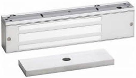
Image: The SDC 1511 Series EMLock (top, rectangular silver unit with mounting holes) and its corresponding armature plate (bottom, flat silver rectangular plate with a central hole).
- Electromagnetic Lock Body: The main unit containing the electromagnet, typically mounted on the door frame.
- Armature Plate: A metal plate designed to be mounted on the door, which is attracted to the electromagnet when energized, securing the door.
Setup and Installation
Proper installation is crucial for the performance and security of the EMLock. It is highly recommended that installation be performed by a certified locksmith or security professional.
- Preparation:
- Ensure all necessary tools and hardware are available.
- Verify the door and frame are structurally sound and can support the lock's weight and holding force.
- Disconnect power to the installation area.
- Mounting the Lock Body:
- Position the electromagnetic lock body on the door frame, typically at the top, ensuring proper alignment with the door's closing edge.
- Mark and drill mounting holes according to the provided template (if applicable).
- Securely fasten the lock body to the door frame using appropriate screws and anchors.
- Mounting the Armature Plate:
- Attach the armature plate to the door, aligning it precisely with the electromagnetic lock body. The armature plate should be able to pivot slightly to ensure full contact with the lock face.
- Use the provided hardware, including any rubber washers or spacers, to allow for slight movement and optimal magnetic contact.
- Wiring:
- Connect the lock to a suitable 12VDC or 24VDC power supply. The lock features autosensing voltage input.
- Ensure all wiring connections are secure and insulated according to electrical standards.
- Integrate with access control systems (keypads, card readers, exit buttons) as required, following their respective wiring diagrams.
- Testing:
- Restore power to the system.
- Test the lock's operation:
- Verify that the door locks securely when power is applied to the EMLock.
- Confirm that the door releases freely when power is removed (or when an exit device is activated).
- Check for any buzzing or rattling, which may indicate improper alignment or loose components.
Operating Instructions
The SDC 1511 EMLock operates on a fail-safe principle, meaning it locks when power is applied and unlocks when power is removed. This is a standard operation for electromagnetic locks.
- Locking: When the door is closed and power is supplied to the EMLock, the electromagnet energizes, creating a strong magnetic bond with the armature plate, thereby securing the door.
- Unlocking: To unlock the door, the power supply to the EMLock must be interrupted. This can be done via an access control system (e.g., keypad entry, card swipe) or an emergency exit device (e.g., push button, motion sensor). Once power is cut, the magnetic bond is released, allowing the door to open.
Maintenance
Regular maintenance ensures the longevity and optimal performance of your SDC 1511 EMLock.
- Cleaning: Periodically clean the face of the electromagnetic lock and the armature plate with a soft, dry cloth. Do not use abrasive cleaners or solvents, as these can damage the finish and performance.
- Inspection: Regularly inspect the lock and armature plate for any signs of wear, damage, or corrosion. Check mounting screws for tightness.
- Alignment: Ensure the armature plate makes full and even contact with the lock face when the door is closed. Misalignment can reduce holding force and cause buzzing.
- Wiring: Periodically check wiring connections for looseness or damage.
Troubleshooting
If you encounter issues with your SDC 1511 EMLock, refer to the following common problems and solutions:
| Problem | Possible Cause | Solution |
|---|---|---|
| Lock does not engage (door does not lock). | No power to the lock; incorrect wiring; faulty power supply; armature plate misalignment. | Check power supply and connections. Verify wiring diagram. Adjust armature plate for full contact. Test power supply output. |
| Lock does not release (door remains locked). | Power not being cut; faulty exit device/access control; short circuit in wiring. | Verify power is being interrupted. Test exit device/access control system. Inspect wiring for shorts. |
| Lock buzzes or rattles. | Armature plate not making full contact; loose mounting screws; uneven mounting surface. | Adjust armature plate position. Tighten all mounting screws. Ensure mounting surfaces are flat. |
| Reduced holding force. | Armature plate not making full contact; dirt/debris on lock face/armature; insufficient power. | Clean lock face and armature plate. Adjust alignment. Verify power supply voltage and current. |
If problems persist after attempting these solutions, contact a qualified technician or SDC customer support.
Specifications
| Brand | SDC |
| Model Number | 1511V |
| Holding Force | 1650 lbs (748 kg) |
| Voltage Input | 12/24 VDC (Autosensing) |
| Material | Metal |
| Finish Type | Polished/Satin |
| Color | Silver |
| Dimensions (Approx.) | 11" Length x 2-3/4" Height x 1-9/16" Depth |
| Item Weight | 11 pounds |
| Certifications | ANSI/BHMA Grade 1 Compliant, UL, CSFM, MEA Listed |
| Recommended Use | Commercial buildings, offices |
| UPC | 712905208916 |
Warranty and Support
For specific warranty information regarding your SDC 1511 Series EMLock, please refer to the documentation provided at the time of purchase or visit the official SDC website. Warranty terms typically cover defects in materials and workmanship under normal use.
For technical support, installation assistance, or to inquire about replacement parts, please contact SDC customer service or your authorized SDC dealer. Ensure you have your product model number (1511V) and purchase details available when seeking support.


