
1. Introduction
This manual provides comprehensive instructions for the installation, operation, and maintenance of the Juniper J2320 Services Router. The J2320 is a high-performance, modular router designed for secure, reliable network connectivity. It features Junos OS, 1GB DRAM, 1GB Flash, and three PIM (Physical Interface Module) slots, suitable for 19-inch rack mounting.
2. Safety Information
Always observe the following safety precautions when handling or operating the Juniper J2320 Services Router:
- Ensure the device is properly grounded before connecting power.
- Do not block ventilation openings. Adequate airflow is crucial for cooling.
- Use only the power supply provided or specified by Juniper Networks.
- Avoid exposing the device to moisture or extreme temperatures.
- Only qualified personnel should perform installation and maintenance.
3. Package Contents
Verify that all items are present in the package:
- Juniper J2320 Services Router
- Base Memory (256 MB)
- SW Encryption
- AC Power Supply
- Rack-mounting hardware (screws, brackets)
- Documentation (this manual)
4. Product Overview
The Juniper J2320 Services Router is a compact, rack-mountable device. Familiarize yourself with its components:

Figure 4.1: Front view of the Juniper J2320 Services Router, showcasing the main unit with its front panel ports and indicators, along with the included power cable and a small bag of mounting screws.

Figure 4.2: Top-down view of the Juniper J2320 Services Router, showing the router unit, a coiled power cable, and a light blue network cable in a plastic bag, all laid out on a white surface.
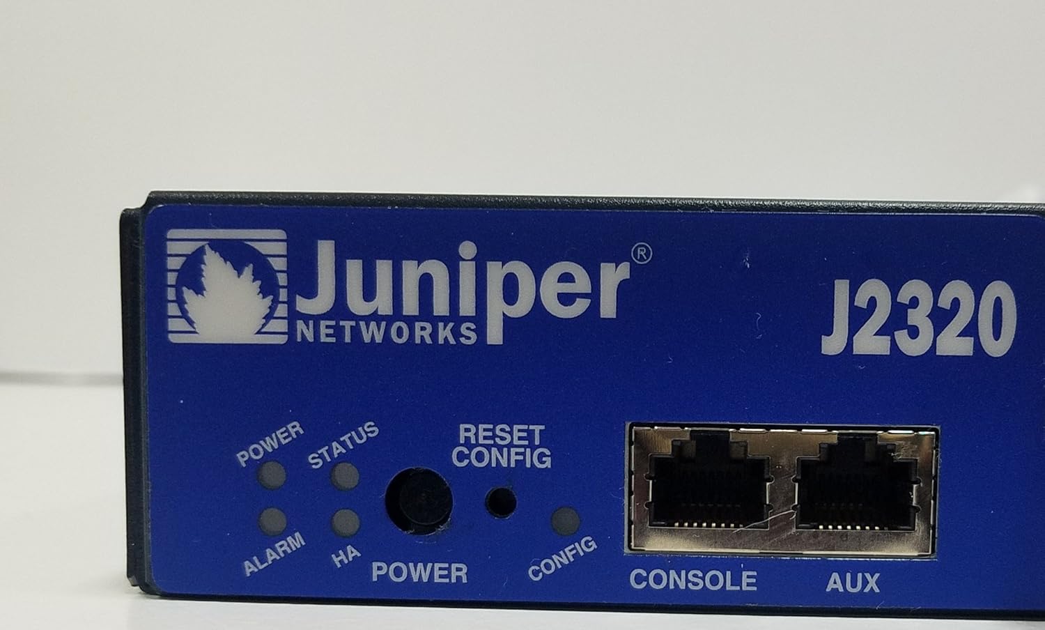
Figure 4.3: A detailed close-up of the Juniper J2320 router's front panel. Visible elements include the Juniper Networks logo, model number J2320, LED indicators for Power, Status, Alarm, and HA (High Availability), a Reset/Config button, and Console and Aux RJ-45 ports.

Figure 4.4: Side profile of the Juniper J2320 Services Router, highlighting the extensive ventilation grilles along the side and rear, essential for heat dissipation during operation.
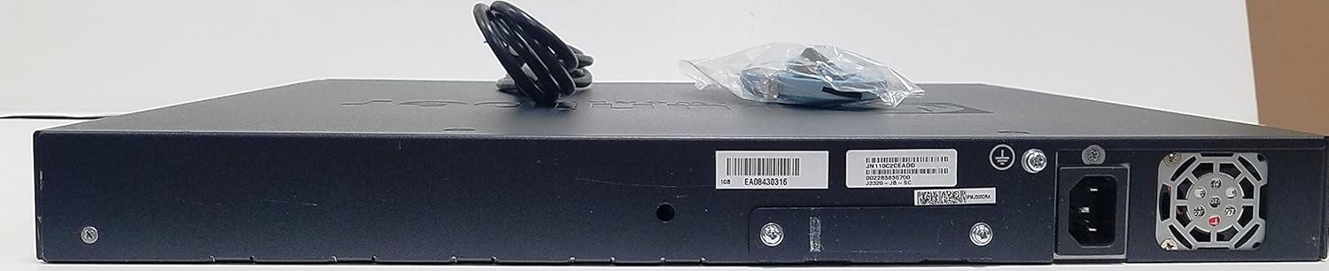
Figure 4.5: Rear view of the Juniper J2320 Services Router, displaying the AC power input socket, grounding screw, and various product labels including serial numbers and model information.
Front Panel Components:
- Power LED: Indicates power status.
- Status LED: Indicates system operational status.
- Alarm LED: Indicates system alarms or errors.
- Reset/Config Button: Used for system reset or configuration mode.
- Console Port: RJ-45 port for local management access.
- Aux Port: Auxiliary port for dial-up or other connections.
- Network (RJ-45) Ports: Four 10/100/1000Base-T Gigabit Ethernet ports.
- PIM Slots: Three expansion slots for Physical Interface Modules.
- USB Ports: Two USB 2.0 ports (USB 0, USB 1).
5. Setup
5.1 Rack Mounting
The J2320 router is designed for 19-inch rack mounting (1U height).
- Attach the provided rack-mounting brackets to the sides of the router using the supplied screws.
- Align the router with the rack posts and secure it using appropriate rack screws.
- Ensure there is adequate space for airflow around the unit.
5.2 Power Connection
- Connect the AC power cord to the power input on the rear of the router.
- Plug the other end of the power cord into a grounded electrical outlet.
- The Power LED on the front panel should illuminate.
5.3 Initial Configuration
For initial configuration, connect a console cable from your management workstation to the Console port on the router's front panel. Refer to the Junos OS documentation for detailed configuration steps.
6. Operating the Router
6.1 Powering On/Off
- Power On: Connect the AC power cord. The router will automatically power on and begin its boot sequence.
- Power Off: Disconnect the AC power cord from the electrical outlet. For graceful shutdown, use the appropriate Junos OS command line interface (CLI) commands before disconnecting power.
6.2 LED Indicators
Monitor the front panel LEDs for operational status:
- Power LED (Green): Solid green indicates power is on.
- Status LED (Green/Amber): Solid green indicates normal operation. Amber may indicate a warning or degraded state.
- Alarm LED (Red/Amber): Red indicates a critical alarm. Amber indicates a minor alarm.
6.3 Network Connectivity
Connect network devices to the RJ-45 network ports. The ports support 10/100/1000Base-T Ethernet. Ensure proper cabling (straight-through or crossover as required by your network setup).
7. Maintenance
7.1 Cleaning
- Periodically clean the exterior of the router with a soft, dry cloth.
- Ensure ventilation openings are free from dust and debris. Use compressed air if necessary, but do not spray directly into ports.
- Do not use liquid or aerosol cleaners.
7.2 Firmware Updates
Regularly check the Juniper Networks support website for the latest Junos OS firmware updates. Keeping the firmware updated ensures optimal performance, security, and access to new features. Follow the instructions provided by Juniper Networks for firmware update procedures.
8. Troubleshooting
| Problem | Possible Cause | Solution |
|---|---|---|
| Router does not power on. | No power to the unit; faulty power cord or outlet. | Check power cord connection. Verify power outlet is functional. |
| Alarm LED is red. | Critical system error or hardware failure. | Check system logs via console. Contact Juniper support if unresolved. |
| Cannot access router via network. | Incorrect IP configuration; network cable issue. | Verify IP settings. Check network cable connections and status LEDs on ports. |
9. Specifications
| Feature | Detail |
|---|---|
| Product Model | J2320 |
| Manufacturer Part Number | J2320-JB-SC |
| Product Type | Router |
| Total Number of Ports | 4 (RJ-45 Network) + Console/Aux + USB |
| Network Technology | 10/100/1000Base-T Gigabit Ethernet |
| Standard Memory | 1GB DRAM |
| Flash Memory | 1GB Flash |
| Expansion Slots | 7 total, 3 PIM slots |
| Compatible Rack Unit | 1U |
| Form Factor | Rack-mountable |
| Dimensions (H x W x D) | 1.8" x 17.5" x 15.1" |
| Weight (Approximate) | 15.00 lb |
| Date First Available | July 21, 2013 |
Note: Memory and Flash values are based on the product title for this specific model variant.
10. Warranty and Support
10.1 Manufacturer's Warranty
The Juniper J2320 Services Router typically comes with a 1-Year Limited Warranty from Juniper Networks. Please refer to the official Juniper Networks warranty documentation for full terms and conditions.
10.2 Extended Protection Plans
Extended protection plans may be available for purchase separately to provide additional coverage beyond the standard manufacturer's warranty. These plans can offer extended service and support for your device.
- 4-Year Protection Plan: Provides extended coverage for four years.
- Complete Protect: A monthly subscription plan covering eligible past and future purchases.
For details on purchasing or activating these plans, consult your retailer or the plan provider.
10.3 Technical Support
For technical assistance, software updates, or further documentation, please visit the official Juniper Networks support website or contact their customer service. Ensure you have your product model and serial number ready when seeking support.
Manufacturer Website Address: http://www.juniper.net


