
1. Introduction
Thank you for choosing the Chieftec Libra Series LG-01B Mid-Tower ATX PC Case. This manual provides essential information for the proper installation, operation, and maintenance of your new computer chassis. Please read this manual thoroughly before beginning installation to ensure optimal performance and safety.
2. Safety Information
Always observe the following safety precautions:
- Ensure the power supply is disconnected from the mains before opening the case or installing components.
- Handle components with care to avoid damage from electrostatic discharge (ESD). Consider using an anti-static wrist strap.
- Keep small parts and tools away from children.
- Do not operate the case in environments with excessive dust, moisture, or extreme temperatures.
- Refer to the manuals of your individual components (motherboard, power supply, etc.) for specific installation instructions.
3. Package Contents
Verify that all items are present in the package:
- Chieftec Libra Series LG-01B PC Case
- Accessory kit (screws, motherboard standoffs, thumb screws)
Note: Power supply unit (PSU) is not included and must be purchased separately.
4. Key Features
- Modern and ergonomic design
- Support for mATX and ATX motherboards
- Front panel connectivity: 1x USB 3.0, 2x USB 2.0, Mic-in, Audio-out (HD Audio)
- Tool-less installation for 5.25" optical drives and 3.5" hard drives
- Drive Bays: 2x 5.25" external, 1x 3.5" external, 2x 3.5" internal, 1x 2.5" internal
- Fan preparations: 1x 80/90/120mm (front), 2x 80mm (rear), 2x 120mm (left side panel)
- Maximum CPU cooler height: 140mm
- Maximum VGA card length: 380mm
5. Setup & Installation
5.1. Opening the Case
To access the interior, remove the side panel. Typically, this involves unscrewing two thumb screws at the rear of the case and sliding the panel backward.
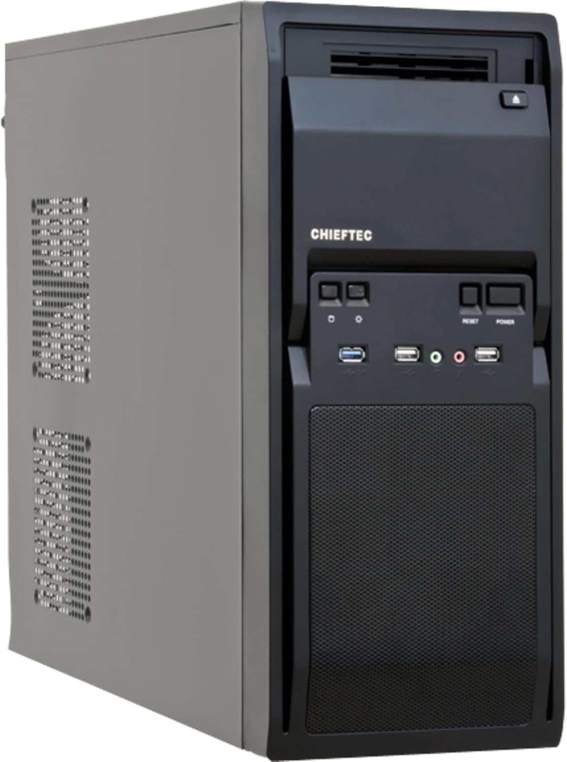
Figure 1: Front-left view of the Chieftec LG-01B PC case, showing the main chassis and front panel design. The side panel is secured by screws at the rear.
5.2. Motherboard Installation
- Install the necessary motherboard standoffs into the motherboard tray according to your motherboard's form factor (ATX or mATX).
- Place the I/O shield into the opening at the rear of the case.
- Carefully align your motherboard with the standoffs and I/O shield, then secure it with screws.

Figure 2: Interior view of the Chieftec LG-01B PC case, showing the motherboard tray, drive bays with tool-less clips, and cable management cutouts. The rear I/O shield opening is visible.
5.3. Power Supply Unit (PSU) Installation
Install your ATX power supply into the designated bay at the top rear of the case and secure it with screws from the exterior.

Figure 3: Rear view of the Chieftec LG-01B PC case, highlighting the power supply mounting area at the top, expansion slots, and fan mounting points.
5.4. Drive Installation (ODD/HDD/SSD)
- 5.25" Optical Drives: Remove the front panel bay cover, slide the optical drive into the bay, and secure it using the tool-less clips.
- 3.5" Hard Drives: Slide the 3.5" HDD into an internal bay and secure it with the tool-less clips.
- 2.5" SSDs: Install 2.5" SSDs into the dedicated internal 2.5" bay, typically requiring screws.

Figure 4: Front view of the Chieftec LG-01B PC case with the front panel cover for the I/O ports opened, revealing the 5.25" and 3.5" external drive bays. The USB and audio ports are also visible.
5.5. Front Panel Connections
Connect the front panel cables (USB 3.0, USB 2.0, HD Audio, Power, Reset, HDD LED, Power LED) to the corresponding headers on your motherboard. Refer to your motherboard manual for header locations.
5.6. Expansion Cards (GPU, etc.)
Remove the necessary expansion slot covers at the rear of the case. Insert your expansion card into the PCIe slot on the motherboard and secure it with a screw.
5.7. Cable Management
Utilize the cable routing cutouts and tie-down points behind the motherboard tray to manage cables for improved airflow and aesthetics.
6. Operating Instructions
Once all components are installed and connected, close the side panel. Connect your monitor, keyboard, mouse, and power cable to the system. Press the power button on the front panel to start your computer.
6.1. Front Panel Ports
- USB 3.0 Port: For high-speed data transfer with compatible devices.
- USB 2.0 Ports: For connecting standard USB devices.
- Mic-in Jack: For connecting a microphone.
- Audio-out Jack: For connecting headphones or speakers.
- Power Button: To turn the system on/off.
- Reset Button: To restart the system.
7. Maintenance
Regular maintenance helps ensure the longevity and optimal performance of your PC components.
- Dust Cleaning: Periodically clean dust from inside the case, especially from fan filters and heatsinks, using compressed air or a soft brush. Ensure the system is powered off and unplugged before cleaning.
- Cable Management: Ensure cables are neatly routed to prevent obstruction of airflow.
- Ventilation: Ensure the case has adequate clearance around its ventilation openings for proper airflow.
8. Troubleshooting
If you encounter issues, consider the following common troubleshooting steps:
- System not powering on:
- Check if the power cable is securely connected to the PSU and the wall outlet.
- Ensure the PSU switch is in the 'ON' position.
- Verify that the front panel power button cable is correctly connected to the motherboard header.
- No display output:
- Ensure the monitor cable is securely connected to the graphics card or motherboard (if using integrated graphics).
- Reseat the graphics card and RAM modules.
- USB ports not working:
- Check if the front panel USB cables are correctly connected to the motherboard headers.
- Ensure necessary drivers are installed for your motherboard.
For more complex issues, consult your component manuals or seek professional assistance.
9. Specifications
| Model | LG-01B |
| Form Factor | Mid Tower |
| Motherboard Compatibility | ATX, mATX |
| Dimensions (LxWxH) | 484mm x 180mm x 404mm (with feet +3mm) / 19.06 x 7.09 x 15.91 inches |
| Weight | 4.5 kg / 9.9 lbs (without PSU) |
| External Drive Bays | 2x 5.25", 1x 3.5" |
| Internal Drive Bays | 2x 3.5", 1x 2.5" |
| Front Panel Ports | 1x USB 3.0, 2x USB 2.0, Mic-in, Audio-out (HD Audio) |
| Fan Preparations | Front: 1x 80/90/120mm; Rear: 2x 80mm; Left Side: 2x 120mm |
| Max CPU Cooler Height | 140mm |
| Max VGA Card Length | 380mm |
| Material Thickness | 0.6mm |
10. Warranty & Support
The Chieftec Libra Series LG-01B PC case comes with a 24-month warranty from the date of purchase. This warranty covers manufacturing defects. It does not cover damage caused by improper installation, misuse, accidents, modifications, or unauthorized repairs.
For technical support or warranty claims, please contact your retailer or visit the official Chieftec website for contact information.


