1. Introduction
This manual provides essential information for the installation, operation, and maintenance of the Schneider Electric Zelio SR2B201BD Logic Relay. Please read this manual thoroughly before using the device to ensure safe and efficient operation.
The Zelio SR2B201BD is a compact programmable logic relay designed for simple automation systems. It features 20 I/O points and operates on a 24Vdc power supply.
2. Safety Information
- Ensure power is disconnected before installation or maintenance.
- Installation and wiring must be performed by qualified personnel in accordance with local and national electrical codes.
- Do not expose the device to moisture, extreme temperatures, or corrosive environments.
- Verify correct voltage supply (24Vdc) before powering on.
3. Product Overview
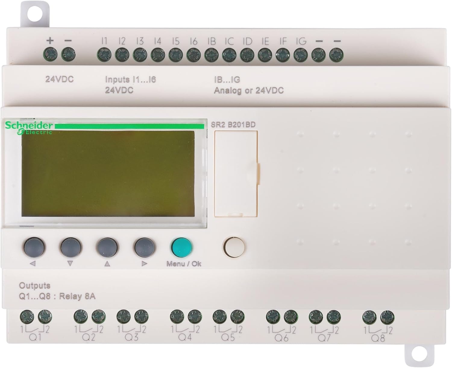
The Schneider Electric Zelio SR2B201BD is a compact logic relay with integrated display and control buttons. It provides various input and output terminals for connecting to sensors, actuators, and other control components.
3.1. Key Features
- 20 I/O points (12 digital inputs, 8 relay outputs)
- 24Vdc power supply
- Integrated LCD display and push-buttons for programming and monitoring
- Compact design for DIN rail mounting
3.2. Dimensions and Weight
- Dimensions: 5.3 x 2.6 x 3.9 inches (134.6 x 66 x 99 mm)
- Weight: 12.6 ounces (357.2 grams)
4. Setup and Installation
4.1. Mounting
The Zelio SR2B201BD is designed for DIN rail mounting. Ensure adequate ventilation around the device.
4.2. Wiring
Refer to the terminal markings on the device for correct wiring connections. Use appropriate wire gauges for all connections.
4.2.1. Power Supply (24Vdc)
- Connect the + terminal to the positive 24Vdc supply.
- Connect the - terminal to the negative 24Vdc supply.
4.2.2. Inputs (I1-I6, IB-IG)
- I1-I6: Digital inputs, 24Vdc. Connect sensors or switches to these terminals.
- IB-IG: Analog or 24Vdc digital inputs. These inputs can be configured for either analog signal reception or digital 24Vdc input.
4.2.3. Outputs (Q1-Q8)
- Q1-Q8: Relay outputs, 8A. These are potential-free contacts for controlling external loads. Connect the load to the respective Q terminal and its common (1L/2L).
5. Operating Instructions
5.1. Powering On
Once all wiring is complete and verified, apply 24Vdc power to the device. The LCD display will illuminate, and the device will initiate its startup sequence.
5.2. Navigation and Programming
Use the navigation buttons (up, down, left, right) to scroll through menus and parameters on the LCD display. Press the Menu/Ok button to select an option or confirm a setting.
- Programming: Programs can be created directly on the device using the function block diagram (FBD) or ladder logic (LAD) editors via the display and buttons. Alternatively, programs can be developed using Zelio Soft 2 software on a PC and then transferred to the relay.
- Monitoring: The display allows real-time monitoring of input/output states, timer values, and counter values.
- Parameter Adjustment: Adjust various operational parameters such as timer presets, counter limits, and input/output configurations.
5.3. Software Integration (Zelio Soft 2)
For advanced programming and easier configuration, use the Zelio Soft 2 software. Connect the logic relay to a PC using the appropriate programming cable (sold separately). The software provides a graphical interface for program development, simulation, and transfer.
6. Maintenance
The Zelio SR2B201BD is designed for minimal maintenance. Regular checks can help ensure long-term reliability.
- Cleaning: Keep the device clean and free from dust. Use a soft, dry cloth for cleaning. Do not use abrasive cleaners or solvents.
- Connections: Periodically check all wiring connections for tightness and signs of corrosion.
- Environment: Ensure the operating environment remains within specified temperature and humidity ranges.
7. Troubleshooting
| Problem | Possible Cause | Solution |
|---|---|---|
| Device does not power on. | No power supply or incorrect voltage. | Verify 24Vdc power supply connections and voltage. Check fuses if applicable. |
| Inputs not responding. | Incorrect wiring, faulty sensor, or program error. | Check input wiring. Test sensor functionality. Review program logic for input conditions. |
| Outputs not activating. | Incorrect wiring, faulty load, or program error. | Check output wiring and load connections. Test load functionality. Review program logic for output conditions. |
| Display shows error message. | Internal fault or programming issue. | Note the error code and consult the detailed Zelio SR2 programming manual or Schneider Electric support. Try resetting the device. |
8. Specifications
| Parameter | Value |
|---|---|
| Model Number | SR2B201BD |
| Brand | Schneider Electric |
| Power Supply | 24 Vdc |
| Digital Inputs | 12 (I1-I6, IB-IG configurable) |
| Analog Inputs | Up to 6 (configurable from IB-IG) |
| Relay Outputs | 8 (Q1-Q8), 8A per output |
| Display | Integrated LCD |
| Mounting | DIN Rail |
| Dimensions (L x W x H) | 5.3 x 2.6 x 3.9 inches (134.6 x 66 x 99 mm) |
| Weight | 12.6 ounces (357.2 grams) |
| Material | Metal |
9. Warranty and Support
9.1. Warranty Information
Schneider Electric products are covered by a standard manufacturer's warranty. For specific warranty terms and conditions, please refer to the documentation provided with your purchase or visit the official Schneider Electric website. Keep your proof of purchase for warranty claims.
9.2. Technical Support
For technical assistance, programming queries, or troubleshooting beyond the scope of this manual, please contact Schneider Electric customer support or visit their official support portal. You can find contact information on the Schneider Electric website: www.se.com


