
1. Introduction
This manual provides essential information for the safe and correct installation, operation, and maintenance of the MITSUBISHI FR-D740-080-NA Inverter Drive. Please read this manual thoroughly before attempting to install or operate the unit. Keep this manual in a safe place for future reference.
1.1 Safety Precautions
Failure to follow these instructions may result in serious injury or equipment damage. Always observe all local and national electrical codes.
- DANGER: Risk of electric shock. Ensure the power supply is completely disconnected and wait at least 10 minutes after power-off before touching any internal components. Verify voltage with a meter.
- WARNING: Proper grounding is essential. Connect the inverter to a reliable ground source to prevent electric shock.
- CAUTION: Installation environment. Install the inverter on a non-combustible surface, away from direct sunlight, excessive dust, corrosive gases, or moisture. Ensure adequate ventilation.
- Qualified personnel only. Installation, wiring, and maintenance should only be performed by qualified and trained personnel.

Figure 1.1: Front view of the FR-D740-080-NA Inverter Drive, highlighting the control panel and integrated safety warnings regarding electrical shock and proper grounding.
2. Setup and Installation
2.1 Mounting
Mount the inverter vertically on a flat, rigid, non-combustible surface. Ensure sufficient space around the unit for proper heat dissipation and ventilation. Avoid mounting in areas subject to vibration or direct impact.
2.2 Wiring
All wiring must comply with local and national electrical codes. Use appropriate wire gauges for the rated current of 8 Amps and 5 HP motor. Ensure all connections are secure to prevent loose contacts, which can cause malfunctions or damage.
- Power Supply (Input): Connect the three-phase 400 VAC power supply to the designated input terminals (R/L1, S/L2, T/L3).
- Motor Connection (Output): Connect the motor to the output terminals (U, V, W).
- Grounding: Connect the ground terminal (E) to a reliable earth ground. This is critical for safety.
- Control Circuit Wiring: Refer to the detailed wiring diagrams in the full product manual for control signal connections (e.g., start/stop, frequency reference, fault output).

Figure 2.1: Side view of the FR-D740-080-NA Inverter Drive, illustrating the heat sink and potential locations for power and control wiring connections.
3. Operating Instructions
3.1 Control Panel Overview
The FR-D740-080-NA features an integrated control panel for basic operation and parameter setting. Key elements include:
- RUN Button: Initiates motor operation.
- STOP/RESET Button: Stops motor operation and resets alarms.
- MODE Button: Toggles between display modes and parameter groups.
- SET Button: Confirms parameter changes.
- PU/EXT Button: Switches between PU (Panel Unit) control and external control modes.
- Dial/Potentiometer: Used for frequency adjustment or parameter value changes.
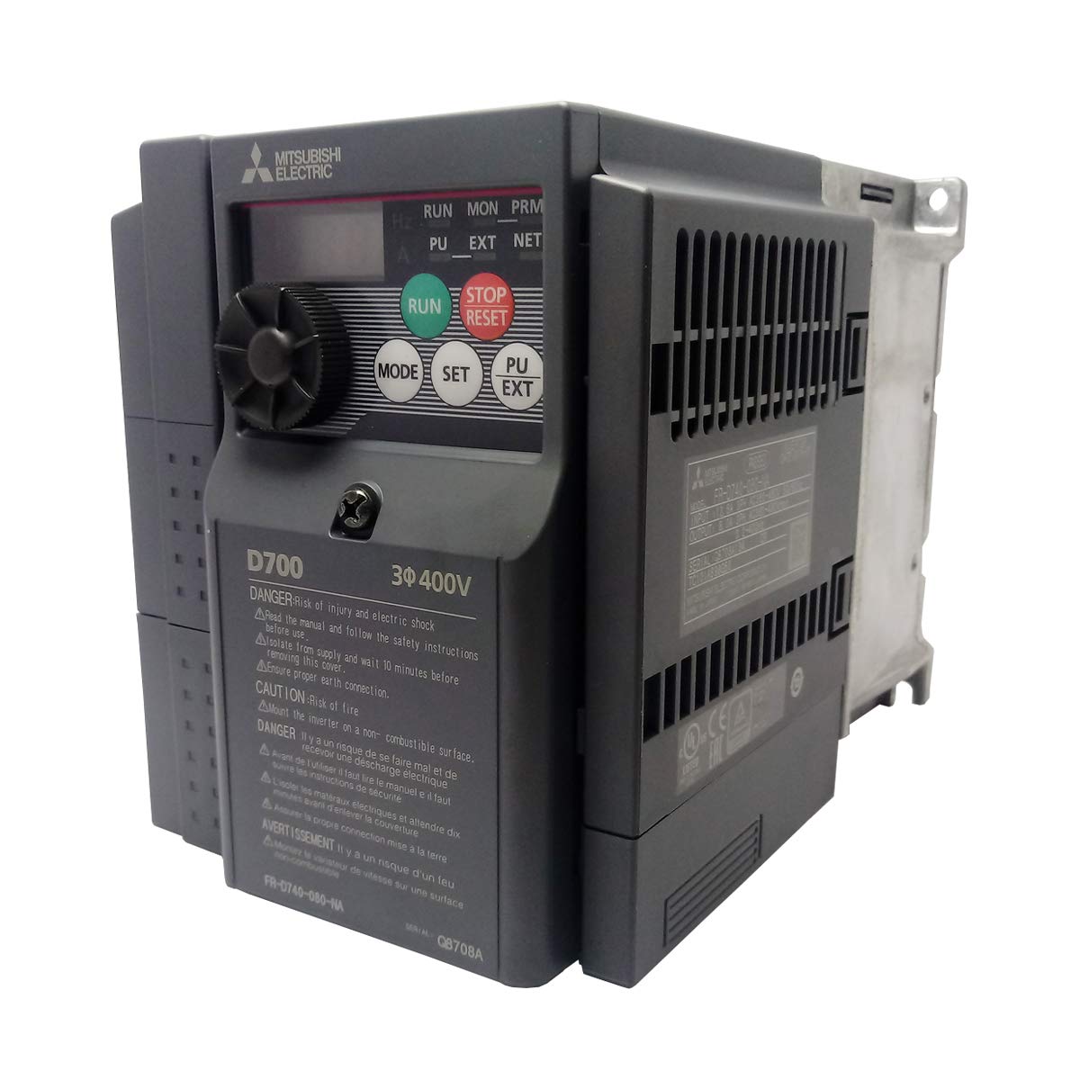
Figure 3.1: The main view of the FR-D740-080-NA Inverter Drive, clearly showing the control panel with its display, RUN, STOP/RESET, MODE, SET, and PU/EXT buttons, and the frequency adjustment dial.
3.2 Basic Operation Sequence
- Ensure all wiring is correct and secure.
- Apply power to the inverter.
- Set the desired operating frequency using the dial or external reference. The drive supports a frequency range of 0.2 to 400 Hz.
- Press the RUN button to start the motor.
- To stop the motor, press the STOP/RESET button.
4. Maintenance
4.1 Routine Inspection
Regular inspection helps ensure reliable operation and extends the lifespan of the inverter. Perform the following checks periodically:
- Check for loose terminal screws and retighten if necessary.
- Inspect for dust accumulation on the heat sink and internal components.
- Look for signs of discoloration or overheating on wiring and components.
- Verify that cooling fans (if present) are operating correctly and not obstructed.
4.2 Cleaning
Use a soft, dry cloth to clean the exterior of the inverter. For internal cleaning, disconnect power and use compressed air to remove dust from the heat sink and circuit boards. Avoid using solvents or abrasive cleaners.
5. Troubleshooting
If the inverter does not operate as expected, consider the following general troubleshooting steps before contacting support:
- No Power: Check the input power supply and circuit breakers. Ensure all power connections are secure.
- Motor Not Running: Verify that the RUN command is active and the frequency reference is set correctly. Check motor wiring.
- Fault Indication: If an error code is displayed, consult the full product manual for specific fault descriptions and corrective actions.
- Overheating: Ensure adequate ventilation and that the ambient temperature is within the specified operating range. Clean any dust from the heat sink.
6. Specifications
Key technical specifications for the MITSUBISHI FR-D740-080-NA Inverter Drive:
| Parameter | Value |
|---|---|
| Model Number | FR-D740-080-NA |
| Series | FR-D700 Series |
| Input Voltage | 400 VAC, Three-Phase |
| Output Frequency Range | 0.2 - 400 Hz |
| Rated Current | 8 Amp |
| Rated Motor Horsepower (HP) | 5 HP |
| Product Dimensions (L x W x H) | 6.96 x 5.04 x 6.96 inches |
| Weight | 3 Pounds |
| Manufacturer | MITSUBISHI |
| Date First Available | September 17, 2013 |
| Part Number (from label) | 1AVF0518072101 |
| Serial Number (from label) | Q8708A134 |

Figure 6.1: Close-up view of the identification label on the FR-D740-080-NA Inverter Drive, displaying the model number, part numbers (1AVF0518072101, 1AVF05ZZ7L4AQ), and serial number (Q8708A134).
7. Support
For further technical assistance, detailed wiring diagrams, advanced parameter settings, or warranty information, please refer to the comprehensive MITSUBISHI FR-D700 Series Inverter Drive manual available from the manufacturer's official website or contact MITSUBISHI customer support directly.
MITSUBISHI Electric Automation, Inc.
For contact information and support resources, please visit the official MITSUBISHI Electric website.


