
SMD DD-1
SMD Distortion Detector DD-1 User Manual
Model: DD-1
1. Introduction
The SMD Distortion Detector DD-1 is an essential tool for audio enthusiasts and professional installers. Its primary function is to accurately set the gain of audio amplifiers and other processors to match the source unit's output level. This ensures a clean, undistorted audio signal, maximizing system performance and protecting your equipment from damage caused by clipping.
The DD-1's circuitry is 100% analog, providing reliable and precise distortion detection. It is designed to operate across a wide range of input signals, making it versatile for various audio applications.
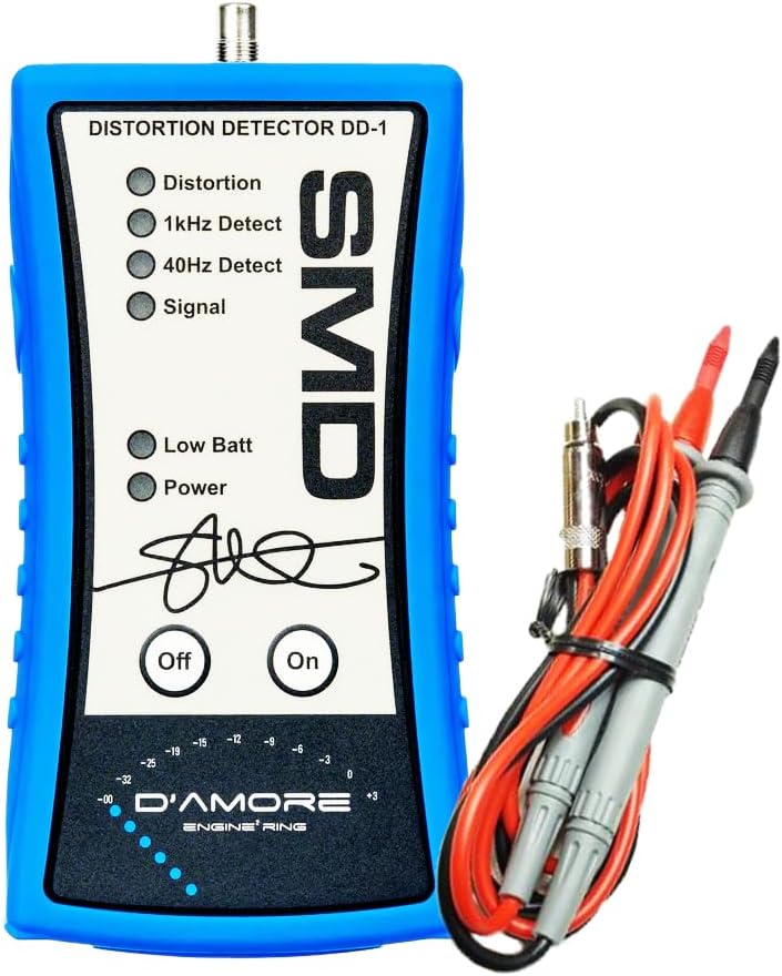
Figure 1.1: The SMD Distortion Detector DD-1 with included test leads.
2. Safety Information
Please read all safety instructions before using the SMD DD-1. Failure to follow these instructions may result in electric shock, fire, or damage to the device or connected equipment.
- Do not expose the device to water or excessive moisture.
- Do not open the casing of the DD-1. There are no user-serviceable parts inside.
- Ensure all connections are secure before applying power to audio equipment.
- Use only the provided test leads or compatible replacements.
- Always disconnect power from audio equipment before making or changing connections.
- Keep out of reach of children.
3. Package Contents
Verify that all items listed below are present in your package:
- SMD Distortion Detector DD-1 Unit
- Test Leads (RCA to bare wire)
- Owner's Manual
- DD-1 Test Tone Disc (CD)
- 1 D Battery (pre-installed or included separately)

Figure 3.1: All components included in the SMD DD-1 package.
4. Setup
Follow these steps to prepare your DD-1 for operation:
- Battery Installation: The DD-1 requires one D battery. The battery compartment is located on the back of the unit. Ensure the battery is inserted with the correct polarity.

Figure 4.1: Rear view of the DD-1, indicating the battery compartment.
- Connecting Test Leads: Connect the provided test leads to the input jack on the top of the DD-1 unit. The RCA connector from the test leads plugs into the DD-1. The bare wire ends of the test leads will connect to the speaker output terminals of your amplifier or processor.

Figure 4.2: Proper connection of test leads to the DD-1 unit.
- Prepare Test Tones: Insert the included DD-1 Test Tone Disc into your source unit (e.g., car stereo CD player). This disc contains specific test tones (e.g., 1kHz, 40Hz) required for accurate gain setting.
5. Operating Instructions
The SMD DD-1 simplifies the process of setting amplifier gains and detecting distortion. Here's how to use it:
5.1. Understanding the Indicators
The DD-1 features several LED indicators and a level meter:
- Distortion LED: Illuminates when harmonic distortion exceeds 1.0%. This is your primary indicator for clipping.
- 1kHz Detect LED: Illuminates when a 1kHz test tone is detected.
- 40Hz Detect LED: Illuminates when a 40Hz test tone is detected.
- Signal LED: Illuminates when an audio signal of at least 750 mVrms is present.
- Low Batt LED: Illuminates when the battery voltage is low and needs replacement.
- Power LED: Illuminates when the unit is turned on.

Figure 5.1: Detailed view of the DD-1's LED indicators.
The D'Amore Engineering level indicators at the bottom provide a visual representation of the signal level, ranging from -32dB to +3dB.
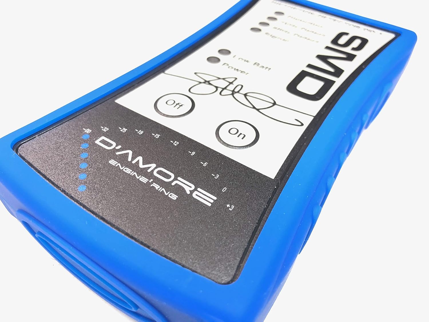
Figure 5.2: The D'Amore Engineering signal level meter.
5.2. Gain Setting Procedure
This procedure outlines the general steps for setting amplifier gains using the DD-1. Refer to your amplifier's manual for specific gain adjustment methods.
- Disconnect Speakers: For safety and accurate measurement, disconnect your speakers from the amplifier outputs.
- Connect DD-1: Connect the DD-1's test leads to the amplifier's speaker output terminals (positive to positive, negative to negative).
- Turn On DD-1: Press the "On" button on the DD-1. The "Power" LED should illuminate.
- Set Source Unit Volume: Play the appropriate test tone from the DD-1 Test Tone Disc (e.g., 1kHz for full-range, 40Hz for subwoofers). Increase your source unit's volume to its maximum clean output level. This is typically 75-80% of the maximum volume, but the DD-1 will help you find the exact point.
- Adjust Amplifier Gain: Slowly increase the gain control on your amplifier. Observe the "Distortion" LED on the DD-1.
- Find Clean Signal: As you increase the gain, the "Signal" LED should be on. Continue increasing the gain until the "Distortion" LED just begins to flicker or illuminate steadily.
- Set Gain Point: Once the "Distortion" LED illuminates, slightly decrease the amplifier gain until the "Distortion" LED turns off. This is your maximum clean gain setting.
- Repeat for Other Channels: If you have a multi-channel amplifier, repeat this process for each channel or pair of channels.
- Disconnect DD-1 and Reconnect Speakers: Once all gains are set, turn off the DD-1, disconnect it from the amplifier, and reconnect your speakers.
The DD-1's operating range of input signal is 1.2 Vrms to 125 Vrms, allowing it to be used with amplifiers producing up to 15,000 watts at 1 ohm.
6. Maintenance
The SMD DD-1 is designed for durability and requires minimal maintenance.
- Cleaning: Wipe the unit with a soft, dry cloth. Do not use abrasive cleaners or solvents.
- Battery Replacement: When the "Low Batt" LED illuminates, replace the D battery promptly to ensure accurate readings.
- Storage: Store the DD-1 in a cool, dry place away from direct sunlight and extreme temperatures.
7. Troubleshooting
| Problem | Possible Cause | Solution |
|---|---|---|
| DD-1 does not power on. | Dead or incorrectly installed battery. | Check battery polarity; replace D battery. |
| "Signal" LED does not illuminate. | No audio signal from amplifier; incorrect connections; signal too low. | Ensure amplifier is on and playing test tone; check test lead connections; increase source unit volume. |
| "Distortion" LED is always on. | Excessive distortion in the signal; amplifier gain too high. | Decrease amplifier gain until the LED turns off. Ensure source unit is not clipping. |
| 1kHz/40Hz Detect LEDs not lighting up. | Incorrect test tone being played; tone not detected. | Ensure the correct frequency test tone is playing from the source unit. |
8. Specifications
| Brand | SMD |
| Model | DD-1 |
| Power Source | Battery Powered (1 D battery included) |
| Distortion Detection Trigger Level | > 1.0% Harmonic Distortion |
| Operating Range of Input Signal | 1.2 Vrms - 125 Vrms |
| Signal Present LED Trigger Voltage | 750 mVrms |
| Item Weight | 9.6 ounces (0.6 Pounds) |
| Product Dimensions (L x W x H) | 10 x 6.25 x 2 inches |
| UPC | 610370312315, 713057261644 |
| Manufacturer | SMD / D'amore Engineering |
9. Warranty and Support
For warranty information and technical support regarding your SMD Distortion Detector DD-1, please refer to the official SMD / D'amore Engineering website or contact their customer service directly. Specific warranty terms may vary and are typically provided with the product at the time of purchase.
It is recommended to register your product, if applicable, to receive updates and support.
Related documentsDD-1


Ask a question about this manual
Ask about setup, troubleshooting, compatibility, parts, safety, or missing instructions. Manuals+ will review the question and use this page’s manual context to help answer it.