
Infineon MOSFET MOSFT 40V 9A 17mOhm 15nC
Infineon MOSFET MOSFT 40V 9A 17mOhm 15nC User Manual
Model: MOSFET MOSFT 40V 9A 17mOhm 15nC
1. Introduction
This manual provides essential information for the proper handling, installation, operation, and troubleshooting of the Infineon MOSFET (Metal-Oxide-Semiconductor Field-Effect Transistor) with specifications of 40V, 9A, 17mOhm, and 15nC. This component is designed for efficient power switching applications.
A MOSFET is a type of field-effect transistor (FET) that is widely used for switching or amplifying electronic signals in electronic devices. It controls the conductivity between its source and drain terminals by applying a voltage to its gate terminal. This particular MOSFET is optimized for low on-resistance and fast switching speeds, making it suitable for various power management circuits.
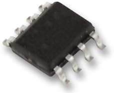
Figure 1: Infineon MOSFET component. This image displays the compact, black plastic package of the MOSFET with eight metallic pins extending from its sides, designed for surface mounting or through-hole integration into circuit boards.
2. Setup and Installation
Proper handling and installation are crucial to prevent damage to the MOSFET and ensure optimal performance. MOSFETs are sensitive to electrostatic discharge (ESD).
2.1. ESD Precautions
- Always wear an anti-static wrist strap connected to a grounded surface when handling the MOSFET.
- Work on an ESD-safe mat.
- Keep the MOSFET in its original anti-static packaging until ready for installation.
- Avoid touching the pins directly.
2.2. Circuit Integration
- Identify Pins: Refer to the datasheet for the specific pinout configuration (Gate, Drain, Source).
- Mounting: Securely mount the MOSFET to the PCB (Printed Circuit Board) using appropriate soldering techniques. Ensure proper heat sinking if the application involves significant power dissipation.
- Connections: Connect the gate, drain, and source terminals to their respective points in your circuit. Pay close attention to polarity and voltage levels.
- Gate Resistor: It is recommended to use a gate resistor to limit current and prevent oscillations during switching.
- Bypass Capacitors: Consider adding bypass capacitors near the MOSFET to stabilize power supply lines, especially for high-frequency switching applications.
3. Operating Principles
The Infineon MOSFET operates as a voltage-controlled switch. Applying a voltage between the gate and source terminals controls the current flow between the drain and source terminals.
3.1. Key Operating Parameters
- Gate-Source Voltage (VGS): This voltage determines whether the MOSFET is in the ON (conducting) or OFF (non-conducting) state. For N-channel MOSFETs, a positive VGS turns the device ON.
- Drain-Source Voltage (VDS): The voltage across the drain and source terminals. Ensure this does not exceed the maximum rated voltage (40V).
- Drain Current (ID): The current flowing through the drain and source. Do not exceed the maximum continuous drain current (9A).
- On-Resistance (RDS(on)): The resistance between the drain and source when the MOSFET is fully ON (17mOhm). Lower RDS(on) means less power dissipation and higher efficiency.
- Gate Charge (QG): The total charge required to turn the MOSFET ON (15nC). This parameter is critical for determining switching speed and gate drive requirements.
3.2. Thermal Management
MOSFETs generate heat during operation, especially when switching or conducting high currents. Adequate thermal management is essential to prevent overheating and ensure long-term reliability.
- Heat Sinks: Use appropriately sized heat sinks for applications with significant power dissipation.
- Thermal Paste: Apply thermal paste between the MOSFET and the heat sink for efficient heat transfer.
- Airflow: Ensure sufficient airflow around the component and heat sink within the enclosure.
- Temperature Monitoring: If possible, monitor the junction temperature to ensure it stays within the specified operating limits.
4. Maintenance and Storage
MOSFETs are solid-state devices and generally require no routine maintenance once installed. However, proper handling and storage are important for their longevity.
4.1. Storage
- Store MOSFETs in their original anti-static packaging in a cool, dry environment.
- Avoid exposure to direct sunlight, extreme temperatures, and high humidity.
- Keep away from strong magnetic fields.
4.2. Cleaning
If cleaning is necessary (e.g., after soldering), use isopropyl alcohol (IPA) and a soft brush or lint-free cloth. Ensure the component is completely dry before applying power.
5. Troubleshooting
If the MOSFET or the circuit it is part of is not functioning as expected, consider the following common issues and their potential solutions.
| Problem | Possible Cause | Solution |
|---|---|---|
| MOSFET not switching ON/OFF | Incorrect gate voltage (VGS), faulty gate drive circuit, damaged MOSFET. | Verify VGS is sufficient to turn ON/OFF. Check gate drive circuit for proper signal and current. Test MOSFET for continuity/shorts. |
| Excessive heat generation | Insufficient heat sinking, exceeding current/voltage ratings, high switching losses, high RDS(on). | Ensure adequate heat sink. Verify ID and VDS are within limits. Optimize gate drive for faster switching. Check for proper ON-state. |
| MOSFET fails (shorted/open) | Overvoltage, overcurrent, ESD damage, reverse polarity, transient spikes. | Check input voltages and currents. Implement protection circuits (e.g., TVS diodes, snubber circuits). Re-evaluate ESD precautions during handling. Replace damaged MOSFET. |
| Unstable operation/Oscillations | Poor PCB layout, long gate traces, lack of gate resistor, parasitic inductance/capacitance. | Optimize PCB layout for short, direct traces. Add gate resistor. Consider snubber circuits. |
Always disconnect power before performing any inspection or repair work on the circuit.
6. Specifications
The following are the key technical specifications for the Infineon MOSFET MOSFT 40V 9A 17mOhm 15nC:
- Product Type: MOSFET (Metal-Oxide-Semiconductor Field-Effect Transistor)
- Brand: Infineon
- Manufacturer: International Rectifier
- Drain-Source Voltage (VDS): 40V (Maximum)
- Continuous Drain Current (ID): 9A (Maximum)
- On-Resistance (RDS(on)): 17mOhm (Typical)
- Gate Charge (QG): 15nC (Typical)
- Package Type: (Not specified, but implied by image as a common surface-mount or small through-hole package)
- ASIN: B005T8ZSG4
- Date First Available: November 1, 2014
For detailed electrical characteristics, thermal information, and package dimensions, please refer to the official Infineon datasheet for this specific component.
Ask a question about this manual
Ask about setup, troubleshooting, compatibility, parts, safety, or missing instructions. Manuals+ will review the question and use this page’s manual context to help answer it.