1. Introduction
This manual provides detailed instructions for the installation, operation, and maintenance of the AGPTEK TA4-SSR Dual Display Digital Programmable PID Temperature Controller. This device is designed for precise temperature regulation across various industrial and home applications, supporting multiple thermocouple types and offering flexible output options.

Figure 1: Front view of the AGPTEK TA4-SSR PID Temperature Controller with active display.
2. Key Features
- Dual Display: Simultaneously shows both Fahrenheit (°F) and Celsius (°C) readings, with a wide temperature range of -1999 to 9999 (dependent on thermocouple).
- Wide Compatibility: Supports various thermocouple sensors (K, J, E, S, T, B, R) and RTD (Pt100, Cu50).
- Flexible Power Options: Operates on 80-265V AC/DC or 12-30V AC/DC.
- Dual Output Capabilities: Features both mechanical relay (3A) and Solid State Relay (SSR) control voltage outputs for diverse applications.
- Advanced Control: Incorporates 3 built-in Auto-Tuning Time Proportion PID Algorithms for precise temperature control.
- Compact Design: DIN 1/16 size (48mm x 48mm x 80mm) for easy integration.
- User-Friendly: One-key operation and Auto-tuning PID/Fuzzy PID control for ease of use.
3. Specifications
| Feature | Specification |
|---|---|
| Display | Dual display for Fahrenheit (°F) and Celsius (°C) |
| Temperature Range | -1999 to 9999 (sensor dependent) |
| Relay Output | Mechanical (3A) and SSR control voltage |
| Accuracy | 0.3% |
| Input Types | Thermocouple (K, J, S, E, T, B, R), RTD (Pt100, Cu50) |
| Power Supply | 80-265V AC/DC or 12-30V AC/DC |
| Consumption | 5VA |
| Dimensions | DIN 1/16 (48mm x 48mm x 80mm) |
| Item Weight | 0.01 Ounces |
4. Setup and Installation
4.1 Physical Installation
The AGPTEK TA4-SSR is designed for panel mounting in a standard DIN 1/16 cutout. Ensure adequate space for ventilation and wiring connections. Use the provided mounting clips to secure the controller firmly in place.

Figure 2: AGPTEK TA4-SSR with mounting clips for panel installation.
4.2 Wiring Connections
Refer to the wiring diagram on the side of the unit and the terminal block on the rear for correct connections. Ensure all power is disconnected before wiring to prevent electrical shock.
- Power Supply: Connect the appropriate AC/DC power (80-265V or 12-30V) to the designated power terminals.
- Sensor Input: Connect your thermocouple or RTD sensor to the input terminals. Ensure correct polarity for thermocouples.
- Output 1 (Relay): Connect your load to the mechanical relay output terminals (rated 3A).
- Output 2 (SSR): Connect your external Solid State Relay (SSR) to the SSR control voltage output terminals. This output provides a low-current signal to switch a high-current SSR.
- Alarm Outputs: Utilize the alarm output terminals for external alarm indicators or control circuits.
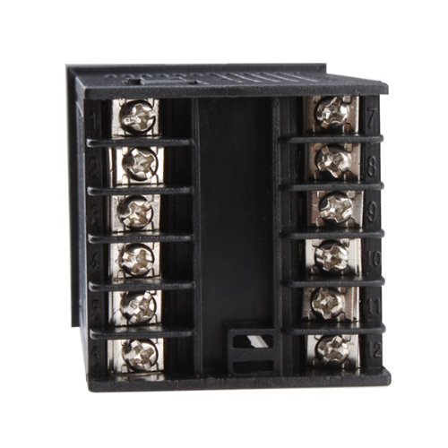
Figure 3: Rear terminal block for wiring power, sensor, and outputs.
5. Operation
5.1 Basic Display and Setpoint
Upon powering on, the upper display (PV) shows the current process value (measured temperature), and the lower display (SV) shows the setpoint temperature. Use the 'SET' button to enter parameter setting mode and the arrow keys to adjust values.
5.2 PID Control and Auto-Tuning
The controller utilizes PID (Proportional-Integral-Derivative) algorithms for precise temperature regulation. For optimal performance, it is recommended to perform an auto-tuning process. This function automatically calculates and sets the optimal P, I, and D parameters for your specific heating/cooling system.
- Initiating Auto-Tuning: Consult the detailed programming guide (usually accessible via the 'SET' button and specific key combinations) to activate the auto-tuning sequence. During auto-tuning, the controller will cycle the output to learn the system's thermal characteristics.
- Manual PID Adjustment: For advanced users, individual P, I, and D parameters, along with other control settings like controlling period and digital filter coefficient, can be manually adjusted.
5.3 Alarm Functions
The controller includes two independent alarm functions (AL1, AL2) that can be configured for various alarm types (e.g., high limit, low limit, deviation). These alarms can trigger external indicators via the alarm output terminals.
6. Maintenance
The AGPTEK TA4-SSR is designed for reliable operation with minimal maintenance. Follow these guidelines:
- Cleaning: Periodically wipe the front panel with a soft, dry cloth. Avoid using abrasive cleaners or solvents.
- Environmental Conditions: Ensure the controller is operated within its specified temperature and humidity ranges. Avoid exposure to excessive dust, moisture, or corrosive gases.
- Connection Checks: Periodically inspect wiring connections for tightness and signs of wear or corrosion.
7. Troubleshooting
If you encounter issues with your AGPTEK TA4-SSR controller, consider the following common troubleshooting steps:
- No Power/Display:
- Verify the power supply connections and voltage.
- Check for blown fuses in the power circuit.
- Incorrect Temperature Reading:
- Ensure the correct sensor type is selected in the controller's parameters.
- Check the sensor wiring for correct polarity and secure connections.
- Inspect the sensor for damage or incorrect placement.
- Output Not Activating/Deactivating:
- Verify the setpoint (SV) and process value (PV) are within expected ranges.
- Check the output wiring and the connected load (e.g., heater, SSR).
- Review control parameters (e.g., PID settings, output mode) to ensure they are configured correctly for your application.
- Unstable Temperature Control:
- Perform an auto-tuning cycle to optimize PID parameters for your system.
- Ensure the sensor is properly located to accurately measure the process temperature.
For issues not resolved by these steps, please refer to the manufacturer's detailed programming guide or contact customer support.
8. Warranty and Support
For warranty information and technical support, please refer to the documentation included with your purchase or visit the official AGPTEK website. Ensure you have your product model (TA4-SSR) and purchase details available when contacting support.


