1. Product Overview
The Johnson Controls EP-8000-3 is an electro-pneumatic transducer designed to convert a standard electrical input signal into a proportional pneumatic output signal. Specifically, it accepts a 4-20 mA DC electrical input and produces a 3-15 PSIG pneumatic output. This device is crucial in industrial control systems for interfacing electronic controllers with pneumatic actuators or other pneumatic equipment. It features a low volume output, ensuring precise and responsive control.
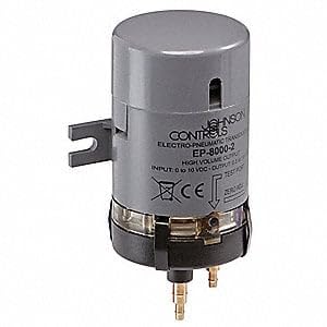
This image displays a Johnson Controls electro-pneumatic transducer, specifically the EP-8000-2 model, which is representative of the EP-8000 series. It is a compact, gray cylindrical unit designed for converting electrical signals to pneumatic signals. Visible features include the brand name 'JOHNSON CONTROLS', model number 'EP-8000-2', input/output specifications, and connection points at the base.
2. Safety Information
Read and understand all instructions before installing, operating, or maintaining this device. Failure to follow these instructions may result in property damage, personal injury, or death.
- Installation and servicing must be performed by qualified personnel only.
- Disconnect all power sources before wiring or servicing the transducer.
- Ensure pneumatic supply lines are depressurized before making or breaking connections.
- Verify that the operating environment is within the specified temperature and humidity ranges.
- Do not exceed the maximum rated input current or output pressure.
3. Setup and Installation
3.1 Mounting
Mount the EP-8000-3 transducer in a location free from excessive vibration, moisture, and extreme temperatures. Ensure adequate space for wiring and pneumatic connections, as well as for future maintenance. The device should be mounted securely to prevent movement during operation.
3.2 Electrical Connections
Connect the 4-20 mA DC input signal to the designated electrical terminals. Observe proper polarity. Use appropriate gauge wiring for the application and ensure all connections are secure to prevent intermittent operation or signal loss. Refer to the device's labeling for specific terminal assignments.
3.3 Pneumatic Connections
Connect the regulated pneumatic supply (typically 20 PSIG for a 3-15 PSIG output range) to the supply port. Connect the output pneumatic line to the designated output port. Ensure all pneumatic connections are leak-free using appropriate fittings and sealing methods. The pneumatic supply must be clean, dry, and oil-free instrument air.
4. Operation
Once properly installed and connected, the EP-8000-3 transducer will convert the incoming 4-20 mA DC electrical signal into a proportional 3-15 PSIG pneumatic output. A 4 mA input will correspond to a 3 PSIG output, and a 20 mA input will correspond to a 15 PSIG output. The transducer operates continuously as long as power and pneumatic supply are provided.
4.1 Calibration (if applicable)
While the EP-8000-3 is factory calibrated, periodic verification of its output against a known input signal is recommended. If field calibration is required, consult the specific calibration procedure outlined in the full technical data sheet or contact Johnson Controls technical support. Typically, calibration involves adjusting zero and span settings to ensure accurate conversion across the full range.
5. Maintenance
The EP-8000-3 transducer is designed for reliable operation with minimal maintenance. However, regular inspection can help ensure optimal performance and longevity.
- Periodic Inspection: Visually inspect the transducer and its connections for any signs of damage, corrosion, or loose wiring/tubing.
- Cleanliness: Keep the exterior of the device clean and free from dust or debris. Do not use harsh chemicals or abrasive cleaners.
- Pneumatic Supply Quality: Ensure the pneumatic supply remains clean, dry, and oil-free. Contaminants can affect the transducer's performance and lifespan.
- Connection Integrity: Periodically check electrical and pneumatic connections for tightness.
6. Troubleshooting
If the EP-8000-3 transducer is not functioning as expected, consider the following troubleshooting steps:
| Symptom | Possible Cause | Action |
|---|---|---|
| No pneumatic output | No electrical input signal; No pneumatic supply; Faulty wiring/tubing; Device failure | Verify 4-20 mA input; Check pneumatic supply pressure; Inspect connections; Replace device if necessary |
| Incorrect pneumatic output | Incorrect input signal; Calibration drift; Incorrect pneumatic supply pressure | Verify 4-20 mA input signal accuracy; Check pneumatic supply pressure; Perform calibration if required |
| Unstable pneumatic output | Fluctuating input signal; Unstable pneumatic supply; Loose connections; Vibration | Check stability of input signal and pneumatic supply; Secure all connections; Reduce vibration if possible |
If troubleshooting steps do not resolve the issue, contact Johnson Controls technical support for further assistance.
7. Specifications
- Model: EP-8000-3
- Manufacturer: JOHNSON CONTROLS
- Input Signal: 4-20 mA DC
- Output Signal: 3-15 PSIG
- Output Type: Low Volume
- Product Type: Electro Pneumatic Transducer
- ASIN: B005KWHVMS
- Date First Available: November 8, 2019
8. Warranty and Support
Specific warranty terms and conditions for the Johnson Controls EP-8000-3 transducer are not detailed within this manual. For information regarding product warranty, technical support, or service, please refer to the official Johnson Controls website or contact your authorized Johnson Controls distributor or sales representative. Ensure you have the product model number (EP-8000-3) and purchase details available when seeking support.