
1. Introduction
The GE TGK12 12H Ground Bar Kit is designed to provide a common grounding point within electrical load centers. This component is essential for safely terminating equipment grounding conductors, ensuring proper electrical system operation and protection against electrical hazards. The TGK12 is a 12-circuit ground bar, suitable for various residential and light commercial electrical installations.
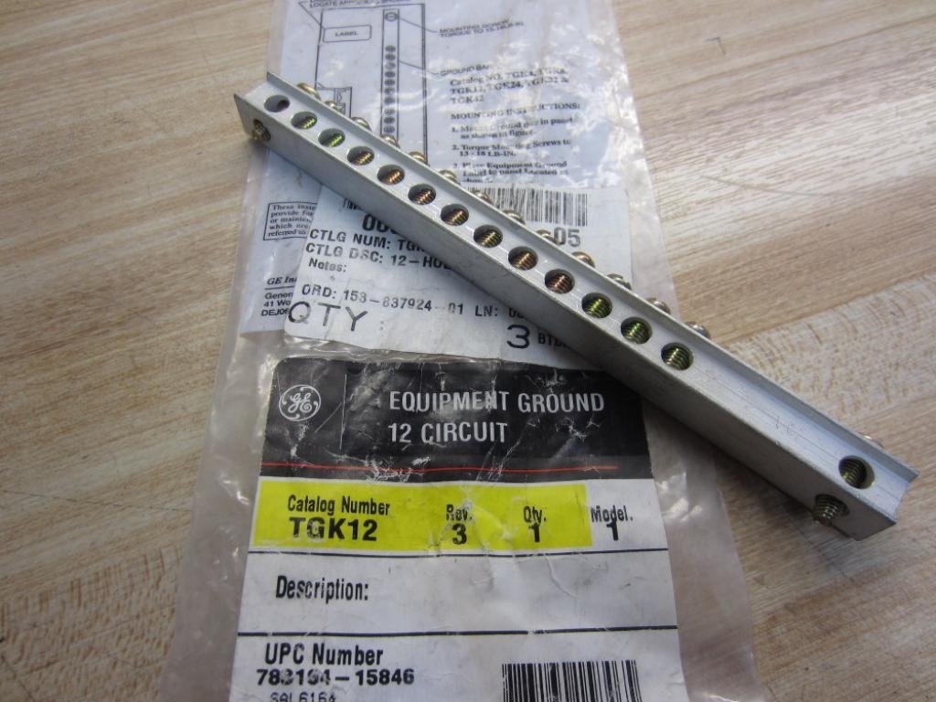
Figure 1: GE TGK12 12H Ground Bar Kit, showing the product within its packaging. This image displays the catalog number TGK12 and UPC 783164158465 on the label.
2. Safety Information
WARNING: Electrical shock hazard. Installation and servicing of this equipment must be performed by qualified personnel only. Always disconnect power at the main service panel before working on electrical equipment. Failure to follow these instructions can result in serious injury or death.
- Ensure all power is OFF before beginning installation.
- Use appropriate personal protective equipment (PPE), including insulated gloves and safety glasses.
- Verify local electrical codes and regulations for proper installation practices.
- Do not exceed the specified wire gauges or number of conductors per terminal.
- Inspect the ground bar for any damage before installation. Do not install damaged components.
3. Setup & Installation
The GE TGK12 ground bar is designed for use with GE PowerMark Gold and PowerMark Plus load centers. It features a panel-mountable design for secure attachment within the load center enclosure.
3.1 Identifying Components
- Ground Bar: The metallic bar with 12 screw terminals.
- Mounting Screws: Typically included for securing the ground bar to the load center chassis.
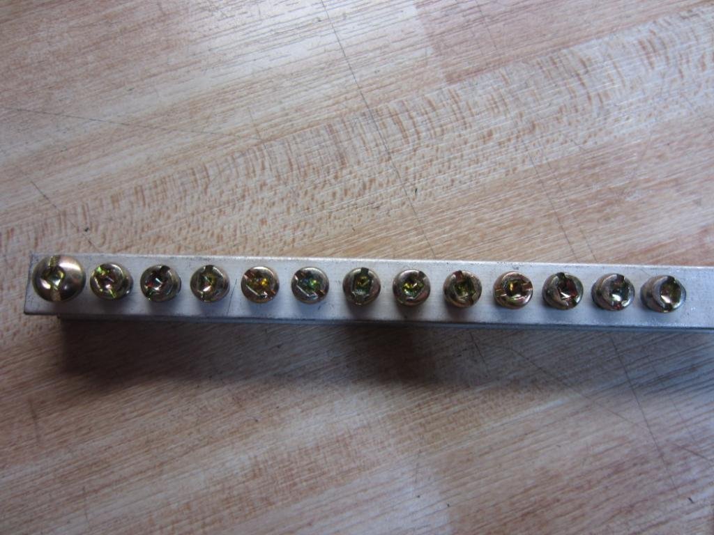
Figure 2: The GE TGK12 ground bar, illustrating its overall structure and potential mounting points. Ensure the ground bar aligns with pre-drilled holes in the load center.
3.2 Mounting Procedure
- Ensure the load center's main power is disconnected.
- Locate the designated mounting holes within the GE PowerMark Gold or Plus load center.
- Position the TGK12 ground bar against the mounting surface, aligning its holes with those in the load center.
- Secure the ground bar using the provided mounting screws. Tighten screws firmly but do not overtighten to avoid stripping.
- Verify that the ground bar is rigidly attached and does not move.
4. Wiring Connections
After the ground bar is securely mounted, equipment grounding conductors can be connected to its terminals. The TGK12 provides 12 individual terminals for this purpose.

Figure 3: A close-up view of the GE TGK12 ground bar, highlighting the individual screw terminals where grounding wires are connected.
4.1 Connecting Ground Wires
- Strip approximately 1/2 inch of insulation from the end of each equipment grounding conductor.
- Insert one stripped wire end into an available terminal opening on the ground bar.
- Using an appropriate screwdriver, tighten the terminal screw firmly. Ensure the wire is securely clamped and cannot be pulled out easily. Refer to the load center's documentation for specific torque requirements.
- Repeat for all equipment grounding conductors.
- Verify that no stray wire strands are present outside the terminal, which could cause a short circuit.
Important: Ensure all connections are tight. Loose connections can lead to overheating and potential fire hazards. If any terminal screws appear stripped or difficult to tighten, do not use that terminal and consult a qualified electrician.
5. Maintenance
The GE TGK12 ground bar requires minimal maintenance. Periodic inspection is recommended to ensure continued safe operation.
- Annual Inspection: With power disconnected, visually inspect the ground bar and all connected wires for any signs of corrosion, loose connections, or damage.
- Cleaning: If dust or debris accumulates, gently clean the ground bar with a dry, non-conductive brush or compressed air. Do not use liquids.
- Tightness Check: Periodically, and always with power off, re-check the tightness of all terminal screws.
6. Troubleshooting
Most issues related to a ground bar are installation-related. If you encounter problems, consider the following:
- Loose Connections: If a circuit experiences intermittent grounding issues, check all terminal screws on the ground bar for tightness.
- Incorrect Ground Bar: Ensure the TGK12 is the correct ground bar for your specific GE PowerMark load center model. Refer to your load center's documentation for compatibility.
- Damaged Terminals: If a terminal screw is stripped or cannot hold a wire securely, do not attempt to force it. This terminal is compromised and should not be used. Consider replacing the ground bar if multiple terminals are affected.
- Corrosion: If corrosion is present, especially in damp environments, it can impede proper grounding. Clean affected areas or replace the ground bar if corrosion is severe.
For any persistent electrical issues, always consult a qualified and licensed electrician.
7. Specifications
| Feature | Detail |
|---|---|
| Model Number | TGK12 |
| Brand | GE Industrial |
| Number of Circuits | 12 |
| Compatibility | GE PowerMark Gold and Plus Load Centers |
| Mounting Type | Panel Mountable |
| Product Dimensions | 1 x 1 x 7 inches |
| Item Weight | 3.04 ounces |
| ASIN | B00529AUO0 |
| Date First Available | August 22, 2012 |
8. Warranty & Support
Specific warranty information for the GE TGK12 12H Ground Bar Kit may vary. Please refer to the documentation provided with your purchase or contact GE Industrial customer support for details regarding warranty coverage and terms.
For technical assistance, product inquiries, or to locate authorized service centers, please visit the official GE Industrial website or contact their customer service department.
GE Industrial Support: www.geindustrial.com/support (Note: This is a placeholder link; please refer to official GE documentation for the correct support URL.)