1. Product Overview
The Derale 13020 Transmission Cooler Mounting Kit provides essential components for installing a remote transmission cooler. This kit is designed for vehicles equipped with 5/16 inch transmission cooler lines and includes a 180-degree Fahrenheit in-line thermostat to regulate fluid temperature. It is compatible with Derale remote mount coolers and can also be used with other compatible cooler models.
Proper installation of this kit ensures efficient operation of your transmission cooler, contributing to the longevity and performance of your vehicle's transmission system.
2. Components List
Before beginning installation, verify that all components listed below are present in your kit:
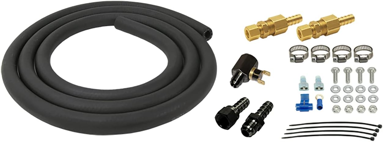
Figure 1: All components included in the Derale 13020 Transmission Cooler Mounting Kit. This includes a coiled black rubber hose, various brass and black compression fittings, a 180-degree F in-line thermostat, metal hose clamps, bolts, washers, nuts, electrical connectors, and zip ties.
- Transmission Hose: Flexible black rubber hose for fluid transfer.
- 5/16 inch Compression Fittings: Brass fittings for secure hose connections (quantity: 2).
- 180°F In-line Thermostat: Thermal switch with electrical terminals to control fluid flow or an auxiliary fan (quantity: 1).
- Hose Barbs/Fittings: Additional black fittings for various connections (quantity: 2).
- Hose Clamps: Metal clamps for securing hose connections (quantity: 4).
- Mounting Hardware: Bolts, washers, and nuts for securing components (quantity: 4 sets).
- Electrical Connectors: Spade terminals, tap connector, and ring terminal for thermostat wiring (various).
- Zip Ties: For securing hoses and wiring (quantity: 4).
3. Setup and Installation
Safety Precautions:
- Ensure the vehicle is turned off, cooled down, and securely supported on jack stands or a lift.
- Disconnect the negative battery terminal before performing any electrical work.
- Wear appropriate personal protective equipment, including safety glasses and gloves.
- Have a drain pan ready to collect any transmission fluid that may spill.
Installation Steps:
- Identify Transmission Cooler Lines: Locate the existing transmission cooler lines on your vehicle. Typically, these run from the transmission to the radiator or an existing cooler. Consult your vehicle's service manual for specific routing.
- Determine Mounting Location: Choose a suitable location for your remote transmission cooler (not included) and the in-line thermostat. Ensure adequate airflow for the cooler and easy access for connections.
- Cut Transmission Line: Carefully cut one of the 5/16 inch transmission cooler lines at the desired point for installing the in-line thermostat or for routing to the remote cooler. Use a sharp hose cutter to ensure a clean cut.
- Install Compression Fittings: Slide a hose clamp onto each end of the cut transmission line. Insert the barbed end of the 5/16 inch compression fittings into the cut lines and secure with the hose clamps. Ensure a tight, leak-free connection.
- Connect Thermostat: Connect the in-line thermostat into the fluid path. The thermostat is designed to open at 180°F, allowing fluid to flow to the remote cooler. Use the provided hose and additional fittings to connect the thermostat to the remote cooler and back to the transmission line. Secure all hose connections with hose clamps.
- Mount Components: Use the provided mounting hardware (bolts, washers, nuts) and zip ties to securely mount the remote cooler, thermostat, and any new hose runs to a stable part of the vehicle chassis. Avoid areas with excessive heat or moving parts.
- Electrical Connection (Thermostat): The 180°F in-line thermostat typically controls an auxiliary fan for the remote cooler. Connect the thermostat's electrical terminals using the provided spade connectors. Route wiring safely away from hot or moving components. Connect one terminal to a fused 12V ignition source and the other to the positive lead of the auxiliary fan. Ensure a proper ground connection for the fan. Consult a wiring diagram if unsure.
- Refill and Check Fluid: After all connections are made and secured, refill the transmission fluid to the manufacturer's recommended level. Start the engine and allow it to reach operating temperature.
- Inspect for Leaks: Thoroughly inspect all new connections for any signs of fluid leaks. Tighten connections as necessary.
4. Operation
Once installed, the Derale 13020 kit facilitates the operation of your remote transmission cooler. The 180°F in-line thermostat plays a crucial role in regulating transmission fluid temperature. When the fluid temperature reaches 180°F, the thermostat will activate (e.g., open a bypass or engage an auxiliary fan), allowing the remote cooler to dissipate excess heat. This ensures that the transmission fluid operates within optimal temperature ranges, preventing overheating and maintaining fluid integrity.
The system operates automatically, requiring no manual intervention during normal driving conditions.
5. Maintenance
Regular inspection of your transmission cooler system is recommended to ensure continued optimal performance:
- Fluid Level Check: Periodically check your transmission fluid level according to your vehicle manufacturer's recommendations.
- Leak Inspection: Visually inspect all hose connections, fittings, and the cooler itself for any signs of transmission fluid leaks. Address any leaks immediately.
- Hose Condition: Check the transmission hoses for cracks, hardening, or signs of wear. Replace any damaged hoses.
- Mounting Security: Ensure all mounted components (cooler, thermostat, hoses) remain securely fastened.
- Electrical Connections: Verify that all electrical connections to the thermostat and auxiliary fan (if applicable) are clean, tight, and free from corrosion.
6. Troubleshooting
If you encounter issues with your transmission cooler system after installing the Derale 13020 kit, consider the following:
- Transmission Overheating:
- Check for proper fluid level.
- Ensure the remote cooler has adequate airflow and is not obstructed.
- Verify the 180°F thermostat is functioning correctly (e.g., activating the fan or opening the fluid path when hot).
- Inspect for kinks or blockages in the transmission lines.
- Fluid Leaks:
- Re-check all hose clamps and compression fittings for tightness.
- Inspect hoses for cuts or punctures.
- Ensure fittings are properly seated and not cross-threaded.
- Thermostat Malfunction:
- Verify electrical connections to the thermostat are secure and receiving power.
- Test the thermostat's continuity or activation point if possible (requires specialized tools).
If troubleshooting steps do not resolve the issue, it is recommended to consult a qualified automotive technician.
7. Specifications
| Feature | Specification |
|---|---|
| Part Number | 13020 |
| Thermostat Activation Temperature | 180°F (82°C) |
| Line Compatibility | 5/16 inch transmission cooler lines |
| Package Dimensions (L x W x H) | 9.25 x 9.25 x 4.75 inches |
| Item Weight | 2.63 pounds (1.19 kg) |
| Country of Origin | United States |
8. Warranty and Support
For information regarding product warranty, technical support, or replacement parts, please contact Derale Performance directly through their official website or customer service channels. Keep your purchase receipt as proof of purchase.
Manufacturer: Derale
Website: www.derale.com


