
Introduction
This manual provides essential information for the installation, operation, and maintenance of the Rheem Ruud Protech Defrost Control Board Kit (Part #47-102685-85). This kit is designed to replace existing defrost control components in compatible Rheem and Ruud HVAC systems, ensuring proper defrost cycles for optimal system performance.
Kit Contents
The 47-102685-85 Defrost Control Board Kit includes the following components:
- 1 x 47-102685-04 Demand Defrost Control Board
- 1 x 47-102709-02 Ambient Sensor (48 inches)
- 1 x 47-102710-02 Defrost Control Sensor (48 inches)
- 2 x 63-22338-02 Screws
- 1 x 64-25340-02 Locking Wing Push Mount Tie
- 1 x 955201 Bracket
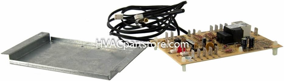
Image: The complete Rheem Ruud Protech Defrost Control Board Kit, showing the main control board, two wired sensors, and a metal mounting bracket. These are the essential components for replacing or upgrading the defrost control system.
Setup and Installation
Safety First: Before beginning any installation, ensure that the power supply to the HVAC unit is completely disconnected at the circuit breaker. Failure to do so can result in serious injury or death.
- Identify Existing Components: Locate the current defrost control board and associated sensors within your HVAC unit. Note the wiring connections and sensor placements. It is recommended to take photographs for reference.
- Remove Old Components: Carefully disconnect all wiring from the old defrost control board and remove it along with its sensors and mounting hardware.
- Mount New Board: Use the provided 955201 Bracket and 63-22338-02 Screws to securely mount the new 47-102685-04 Demand Defrost Control Board in the designated location. The 64-25340-02 Locking Wing Push Mount Tie can be used for cable management.
- Connect Sensors: Install the new 47-102709-02 Ambient Sensor and 47-102710-02 Defrost Control Sensor. Ensure they are placed in the correct locations as specified by your HVAC unit's service manual. Connect the sensor wires to the appropriate terminals on the new control board.
- Wire Connections: Reconnect all other necessary wiring (e.g., power, compressor, fan) to the new control board, following the wiring diagram of your specific Rheem/Ruud model. Ensure all connections are secure and correct.
- Verify Compatibility: This kit is compatible with various Rheem/Ruud models, including but not limited to: -JNL-A072, -JNL-B090, -JNL-B120, 13PJL18, 13PJL24, 13PJL30, 13PJL36, 13PJL42, 13PJL48, 13PJL60 (all 13PJL date codes after 1206), 14PJM18, 14PJM24, 14PJM30, 14PJM36, 14PJM42, 14PJM48, 14PJM60, 15PJL18, 15PJL24, 15PJL30, 15PJL36, 15PJL42, 15PJL48, 15PJL60.
- Restore Power: Once all connections are verified, restore power to the HVAC unit.
It is highly recommended that installation be performed by a qualified HVAC technician to ensure proper and safe operation.
Operating Principles
The Demand Defrost Control Board manages the defrost cycle of your heat pump system. It utilizes input from the ambient sensor (measuring outdoor temperature) and the defrost control sensor (measuring coil temperature) to determine when a defrost cycle is necessary. This demand-based approach helps to optimize energy efficiency by initiating defrost only when required, rather than on a fixed timer.
During normal operation, the board monitors these sensor inputs. If ice accumulation is detected on the outdoor coil, the board will initiate a defrost cycle, typically by reversing the refrigerant flow and activating the auxiliary heat. Once the coil is clear of ice, the board will terminate the defrost cycle and return the system to normal heating or cooling operation.
Some control boards feature diagnostic LEDs. For this board, if both lights flash at the same time, it indicates normal operation. If the lights alternate, the system may be in a 5-minute lockout period, after which it should reset.
Maintenance
As an electronic component, the defrost control board itself requires minimal direct maintenance. However, regular maintenance of your overall HVAC system is crucial for the longevity and proper functioning of the board and the entire unit.
- System Cleanliness: Ensure the outdoor coil is kept clean and free of debris to prevent excessive ice buildup, which can overwork the defrost system.
- Sensor Integrity: Periodically inspect the ambient and defrost sensors for physical damage or corrosion. Ensure their connections to the board are secure.
- Wiring Inspection: Check all wiring connections to the board for tightness and signs of wear or damage.
Always disconnect power before performing any inspection or maintenance on the HVAC unit.
Troubleshooting
If your HVAC system is experiencing issues related to defrosting or overall operation after installing this kit, consider the following troubleshooting steps:
- No Defrosting or Excessive Ice: Verify that both the ambient and defrost control sensors are correctly installed and connected. Check for any breaks or shorts in the sensor wiring.
- System Lockout: If the diagnostic LEDs on the board are alternating, the system may be in a temporary lockout. Wait approximately 5 minutes to see if the board resets.
- No Power to Board: Check the power supply to the HVAC unit and the connections to the control board. Ensure circuit breakers are not tripped.
- Incorrect Operation: Double-check all wiring connections against the HVAC unit's wiring diagram. Incorrect wiring can lead to improper function.
- Faulty Component: While rare, a component within the kit could be defective. If all other troubleshooting steps fail, professional diagnosis may be required to test the board and sensors.
For complex issues or if you are unsure about any step, consult a certified HVAC technician.
Specifications
| Feature | Detail |
|---|---|
| Product Name | Defrost Control Board Kit |
| Model Number | 47-102685-85 |
| Brand | ProTech (Rheem/Ruud Compatible) |
| Included Components |
|
| Replaces Part Numbers | 47-102685-02, 47-21517-22, 47-21517-92, 47-102685-83, 47-102685-04, 47-102684-02 |
| Compatible Models | -JNL-A072, -JNL-B090, -JNL-B120, 13PJL18, 13PJL24, 13PJL30, 13PJL36, 13PJL42, 13PJL48, 13PJL60 (all 13PJL Date code after 1206), 14PJM18, 14PJM24, 14PJM30, 14PJM36, 14PJM42, 14PJM48, 14PJM60, 15PJL18, 15PJL24, 15PJL30, 15PJL36, 15PJL42, 15PJL48, 15PJL60 |
Warranty Information
Warranty coverage for the Rheem Ruud Protech Defrost Control Board Kit is typically provided by the manufacturer or the seller at the point of purchase. Please refer to your purchase documentation or contact the vendor directly for specific warranty terms and conditions.
Support
For technical assistance, installation guidance, or troubleshooting beyond the scope of this manual, it is recommended to contact a qualified HVAC professional or the manufacturer's customer support. Contact information for ProTech or Rheem/Ruud can typically be found on their official websites or through your product supplier.