
1. Introduction
This manual provides essential information for the safe and efficient installation, operation, and maintenance of the PILZ PNOZ s3 Safety Relay, Model 751103. The PNOZ s3 is designed for monitoring safety functions such as E-STOP pushbuttons, safety gates, and light grids in industrial applications.
1.1 Safety Information
- Read this manual thoroughly before installation or operation.
- Installation and maintenance must be performed by qualified personnel only.
- Observe all local and national safety regulations.
- Disconnect power before performing any work on the device.
2. Product Description
The PILZ PNOZ s3 is a compact safety relay from the PNOZ X series, specifically designed for monitoring safety circuits. It features 2 normally open (n/o) contacts and operates on a 24VDC supply. This device is suitable for applications requiring reliable monitoring of E-STOP functions, safety gates, and light curtains, ensuring machine and personnel safety.
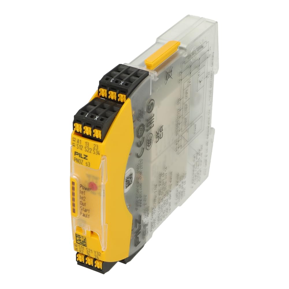
Figure 1: PILZ PNOZ s3 Safety Relay. The image displays the front face of the relay with terminal markings (A1, A2, S11, S12, S21, S22, S34, 13, 23, X1, X3) and LED indicators for Power, In1, In2, Out, Start, and Fault. The transparent housing reveals internal components and a wiring diagram on the side.
3. Technical Specifications
| Feature | Specification |
|---|---|
| Brand | PILZ |
| Model Number | 751103 |
| Product Dimensions | 3.54 x 6.69 x 14.96 inches |
| Item Weight | 4.8 ounces |
| Controller Type | Button Control |
| Number of Buttons | 2 |
| Max Number of Supported Devices | 1 |
| Special Feature | Ergonomic |
Note: Specifications are subject to change without prior notice. Refer to the official PILZ documentation for the most current information.
4. Setup and Installation
4.1 Mounting
The PNOZ s3 safety relay is designed for DIN rail mounting. Ensure the mounting location is free from excessive vibration, moisture, and extreme temperatures. Allow adequate space for ventilation and wiring.
4.2 Wiring Connections
Refer to the wiring diagram printed on the side of the device and the terminal markings on the front for correct connections. Ensure all connections are secure and comply with electrical codes.
- Power Supply: Connect 24VDC to terminals A1 and A2.
- Input Circuits: Connect safety devices (E-STOP, safety gate, light grid) to input terminals such as S11, S12, S21, S22, S34. The specific configuration depends on the safety function being monitored.
- Output Contacts: The safety relay provides 2 normally open (n/o) contacts for controlling the safe state of machinery. Connect these to terminals 13, 23, etc., as per your application's requirements.
- Start Circuit: If an automatic start is not desired, a manual start button can be connected to the appropriate start input (e.g., X1, X3).
Caution: Incorrect wiring can lead to dangerous situations and damage to the device. Always verify wiring before applying power.
5. Operating Instructions
5.1 Power-Up and Initial Check
- After completing all wiring, apply 24VDC power to the device.
- Observe the LED indicators on the front panel.
- The "Power" LED should illuminate, indicating the device is receiving power.
- Other LEDs (In1, In2, Out, Start, Fault) will indicate the status of the safety inputs, outputs, and any detected faults.
5.2 Normal Operation
When all safety inputs are closed (e.g., E-STOP released, safety gate closed), and the start condition is met (manual start pressed or automatic start enabled), the output contacts (13-14, 23-24) will close, allowing the connected machinery to operate. If any safety input opens, the output contacts will immediately open, bringing the machinery to a safe stop.
5.3 LED Indicators
- Power: Indicates power supply status.
- In1, In2: Indicate the status of the safety input circuits.
- Out: Indicates the status of the safety output contacts.
- Start: Indicates the status of the start circuit.
- Fault: Illuminates if an internal fault or wiring error is detected.
6. Maintenance
The PILZ PNOZ s3 safety relay is designed for minimal maintenance. However, regular inspections are recommended to ensure continued safe operation.
- Visual Inspection: Periodically check the device for any signs of physical damage, discoloration, or loose connections.
- Function Test: Regularly test the safety function being monitored (e.g., activate E-STOP, open safety gate) to ensure the relay responds correctly and brings the machine to a safe state.
- Cleaning: If necessary, clean the exterior of the device with a soft, dry cloth. Do not use abrasive cleaners or solvents.
Warning: Do not attempt to repair the device. Refer all servicing to authorized PILZ service personnel.
7. Troubleshooting
This section provides guidance for common issues. For complex problems, contact PILZ technical support.
- Device not powering on (Power LED off):
- Check 24VDC power supply connections to A1 and A2.
- Verify the power supply is active and providing the correct voltage.
- Output contacts not closing (Out LED off, but inputs are closed):
- Check the status of all input LEDs (In1, In2). Ensure they indicate closed safety circuits.
- Verify the start circuit (Start LED) is active or the manual start button has been pressed.
- Check for a "Fault" LED indication.
- Fault LED illuminated:
- Indicates an internal fault or a wiring error in the safety circuit.
- Review all wiring connections against the diagram.
- Consult the detailed fault codes in the official PILZ PNOZ s3 documentation for specific fault diagnosis.
8. Warranty and Support
For warranty information, technical support, or service requests, please contact PILZ directly or your authorized PILZ distributor. Ensure you have the model number (751103) and serial number of your device available when contacting support.
PILZ Contact Information:
- Visit the official PILZ website for contact details in your region.
- Refer to the documentation included with your product for specific support contacts.


