1. Product Overview
This manual provides detailed instructions for the installation, operation, and maintenance of the Supermicro X8DTL-IF-B Dual LGA1366 Xeon/Intel 5500/ DDR3/ V&2GbE/ ATX Server Motherboard. The Supermicro X8DTL-IF-B is designed for server applications, supporting dual Intel Xeon 5500 series processors and DDR3 ECC/REG memory, offering robust performance and reliability for demanding computing environments.
2. Setup and Installation
Before beginning installation, ensure your workspace is clean, well-lit, and free of static electricity. Use an anti-static wrist strap to prevent damage to components.
2.1 Motherboard Layout
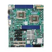
Image Description: An overhead view of the Supermicro X8DTL-IF-B server motherboard. Key components visible include the dual LGA1366 CPU sockets, six DDR3 DIMM slots, various PCI-Express and PCI expansion slots, SATA ports, and I/O panel connectors. This image illustrates the general layout and placement of major components on the motherboard.
2.2 CPU Installation
- Locate the two LGA1366 CPU sockets on the motherboard.
- Open the CPU socket retention mechanism by pushing down and away from the socket.
- Carefully align the CPU with the socket, ensuring the triangular gold arrow on the CPU matches the arrow on the socket. Do not force the CPU into place.
- Gently lower the CPU into the socket.
- Close the retention mechanism, ensuring it locks securely.
- Apply thermal paste to the CPU and install the appropriate CPU cooler. Repeat for the second CPU.
2.3 Memory Installation
- The motherboard supports 6x 240-pin DDR3-1333/1066/800 DIMMs, ECC/REG, up to 48GB.
- Open the clips at both ends of the DIMM slot.
- Align the memory module with the slot, ensuring the notch on the DIMM matches the key in the slot.
- Press down firmly on both ends of the DIMM until the clips snap into place.
- For optimal performance, install memory modules in matched pairs or triplets according to the motherboard's memory channel configuration.
2.4 Motherboard Mounting and Connections
- Install the I/O shield into the server chassis.
- Carefully place the motherboard into the chassis, aligning the screw holes with the standoffs.
- Secure the motherboard with screws.
- Connect the 24-pin ATX power connector and the 8-pin (or 4-pin) CPU power connectors from the power supply to the motherboard.
- Connect SATA data cables to the 6x SATA2 ports and to your storage devices.
- Connect front panel headers (power switch, reset switch, HDD LED, power LED, USB ports) according to the motherboard manual.
- Install any necessary expansion cards into the PCI-Express or PCI slots.
3. Operating Instructions
3.1 Initial Power-On
After all components are installed and connected, ensure the power supply is switched on. Press the power button on the front panel of your server chassis. The system should initiate the Power-On Self-Test (POST).
3.2 BIOS/UEFI Setup
During POST, press the designated key (usually DEL or F2) to enter the BIOS/UEFI setup utility. Here you can configure boot order, system time, CPU settings, memory timings, and other hardware parameters. Refer to the detailed Supermicro BIOS manual for specific settings.
3.3 Operating System Installation
Once BIOS settings are configured, you can proceed with installing your preferred operating system (e.g., Windows Server, Linux distributions). Boot from your installation media (USB drive or optical disc) and follow the on-screen prompts.
3.4 IPMI Remote Management
The X8DTL-IF-B features a dedicated IPMI LAN port for remote management. Connect this port to your network. You can access the IPMI interface via a web browser to monitor system health, manage power, and even install operating systems remotely. Consult the Supermicro IPMI User's Guide for detailed instructions on configuration and usage.
4. Maintenance
4.1 Cleaning
Regularly clean the interior of your server chassis to prevent dust buildup, which can lead to overheating and component failure. Use compressed air to remove dust from fans, heatsinks, and motherboard components. Ensure the system is powered off and unplugged before cleaning.
4.2 Firmware Updates
Periodically check the Supermicro website for updated BIOS, IPMI, and driver firmware. Keeping your system's firmware up-to-date can improve stability, performance, and security. Follow Supermicro's instructions carefully when performing firmware updates.
4.3 Component Checks
Occasionally inspect all cable connections (power, data, front panel) to ensure they are secure. Check cooling fans for proper operation and listen for unusual noises.
5. Troubleshooting
This section provides solutions to common issues you might encounter.
5.1 No Power
- Ensure the power supply is connected to a working outlet and switched on.
- Verify all power cables (24-pin ATX, 8-pin CPU) are securely connected to the motherboard.
- Check the front panel power switch connection to the motherboard.
- Test the power supply with another system or a power supply tester.
5.2 No Display Output
- Ensure the monitor is connected to the motherboard's VGA port and is powered on.
- Verify that the CPU(s) and memory modules are correctly installed.
- Try booting with only one memory module installed in the primary slot.
- Clear the CMOS (Complementary Metal-Oxide-Semiconductor) by removing the CMOS battery for a few minutes or using the clear CMOS jumper (refer to the motherboard diagram).
5.3 System Fails to Boot / POST Errors
- Listen for beep codes from the system speaker, which can indicate specific hardware issues. Consult the Supermicro manual for beep code definitions.
- Check all installed expansion cards and ensure they are seated correctly.
- Disconnect all non-essential peripherals and try booting.
- Verify that the boot device (HDD/SSD) is properly connected and configured in the BIOS.
6. Specifications
| Feature | Detail |
|---|---|
| Model Number | X8DTL-IF-B |
| CPU Support | Dual LGA1366 Sockets, Supports Intel 64-bit Quad Core Xeon Processor 5500 sequence (Nehalem-EP processor), QPI Upto 6.4 GT/s |
| Chipset | Intel 5500 (Tylersburg) & ICH10R + IOH-24D |
| Memory | 6x 240pin DDR3-1333/1066/800 DIMMs, ECC/REG, Upto 48GB; Memory Mirroring supported |
| Expansion Slots | 1x PCI-Express x16 (runs on x8, Support PCI-Express 2.0); 2x PCI-Express x8 (one runs on x4, Support PCI-Express 2.0); 1x PCI-Express x8 (runs on x4); 2x 33MHz PCI Slots |
| SATA Ports | 6x SATA2 Ports, Support RAID 0, 1, 5, 10 |
| USB Ports | 5x USB 2.0 Ports (2 rear, 2 by headers and 1 on-board) |
| Other I/O Ports | 2x PS/2 Ports; 2x Serial Ports (1 rear, 1 by header); 1x VGA Port; 2x RJ45 LAN Ports; 1x RJ45 Dedicated IPMI LAN Port |
| Video | Matrox G200eW Graphics Controller |
| Form Factor | ATX |
| Dimensions (LxWxH) | 12 x 2.2 x 10 inches |
| Weight | 5 pounds |
| First Available Date | November 2, 2010 |
7. Warranty and Support
For detailed warranty information, technical support, and the latest drivers and firmware updates, please refer to the official Supermicro website or contact your point of purchase.
Supermicro Official Website: www.supermicro.com


