
1. Introduction
The Interlogix NetworX NX-216E is a 16-zone hardwired expansion module designed to extend the zone capacity of compatible Interlogix NetworX security control panels, specifically the NX-8 and NX-8E systems. This module allows for the integration of additional hardwired detection devices, such as door/window contacts, motion detectors, and glass break sensors, into your security system. It connects to the control panel via the data bus and provides 16 additional programmable zones.
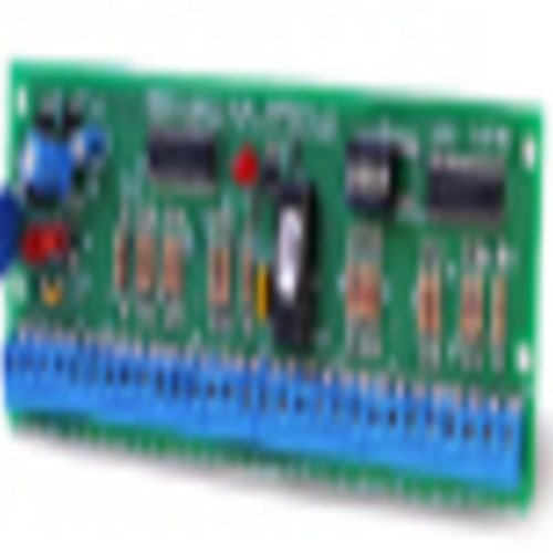
Figure 1: Interlogix NetworX NX-216E 16-Zone Hardwired Expansion Module.
2. Safety Information
Please read all instructions carefully before installing or operating the NX-216E module. Failure to follow these instructions may result in damage to the product, property, or personal injury.
- Qualified Personnel: Installation and servicing should only be performed by qualified security technicians.
- Power Disconnection: Always disconnect power from the main control panel before installing, wiring, or servicing the NX-216E module.
- Static Discharge: Take precautions to prevent electrostatic discharge (ESD) when handling the module to avoid damaging sensitive electronic components.
- Wiring: Ensure all wiring is correctly connected according to the wiring diagrams provided in this manual and the main control panel's manual. Incorrect wiring can cause malfunctions or damage.
- Environment: Install the module in a dry, indoor location, away from direct sunlight, extreme temperatures, and moisture.
3. Setup and Installation
3.1. Mounting the Module
- Select a suitable location inside the main control panel enclosure or a separate secure enclosure.
- Ensure adequate space for wiring and ventilation.
- Mount the NX-216E module using the provided standoffs or screws, securing it firmly to the backplate of the enclosure.
3.2. Wiring Connections
The NX-216E connects to the main control panel via the 4-wire data bus (RED, BLK, YEL, GRN) and provides terminals for 16 hardwired zones.
- Data Bus Connection:
- Connect the RED terminal on the NX-216E to the RED terminal on the control panel.
- Connect the BLK terminal on the NX-216E to the BLK terminal on the control panel.
- Connect the YEL terminal on the NX-216E to the YEL terminal on the control panel.
- Connect the GRN terminal on the NX-216E to the GRN terminal on the control panel.
- Zone Wiring:
- Connect your hardwired detection devices to the zone terminals (Z1-Z16) and common (COM) terminals on the NX-216E.
- Refer to the specific wiring requirements for each detection device (e.g., normally open, normally closed, end-of-line resistor configuration).
- Ensure proper end-of-line (EOL) resistor placement as required by your control panel's programming for each zone. Typically, EOL resistors are 2.2k Ohm.
3.3. Addressing and Programming
The NX-216E module requires addressing and programming within the main control panel to be recognized and function correctly.
- Module Addressing: The NX-216E typically uses a default address or can be assigned one via jumpers or DIP switches on the module itself. Consult the module's specific documentation for addressing procedures.
- Control Panel Programming:
- Access the programming mode of your NX-8 or NX-8E control panel (refer to your main panel's manual for specific steps).
- Locate the section for configuring zone expander modules.
- Enable the zones corresponding to the NX-216E (zones 9-24 if it's the first expander, or higher if multiple expanders are used).
- Program each zone (type, response time, attributes) according to the connected device and desired system behavior.
- Save and exit programming mode.
4. Operating the Module
The NX-216E is an expansion module and does not have direct user-operable controls. Once properly installed and programmed, it functions as an extension of the main control panel, providing additional zone inputs. The operation of these zones is managed entirely through the main NX-8/NX-8E control panel and its associated keypads.
- Zone Status: The status of zones connected to the NX-216E (open, closed, alarm) will be displayed on the system keypad, just like the zones directly on the main panel.
- Arming/Disarming: Arming and disarming the security system will activate or deactivate all programmed zones, including those on the expander module.
- Trouble Conditions: Any trouble conditions related to the expander module or its connected zones (e.g., tamper, fault) will be reported by the main control panel.
5. Maintenance
The NX-216E module requires minimal maintenance. Regular checks of the overall security system are recommended.
- Visual Inspection: Periodically inspect the module and its wiring for any signs of damage, loose connections, or corrosion.
- Cleaning: If necessary, gently clean the module with a soft, dry cloth. Do not use liquid cleaners or solvents.
- System Testing: Regularly test all zones connected to the NX-216E as part of your routine security system testing to ensure proper functionality.
6. Troubleshooting
If you encounter issues with your NX-216E module, consider the following troubleshooting steps:
- Module Not Recognized:
- Verify all data bus connections (RED, BLK, YEL, GRN) are secure and correctly wired between the NX-216E and the main control panel.
- Ensure the module's address is correctly set (if applicable) and programmed into the main control panel.
- Check for power to the module (indicated by an LED on some models).
- Zones Not Responding:
- Confirm that the specific zones on the NX-216E are enabled and correctly programmed in the main control panel.
- Inspect the wiring for the affected zone(s) for breaks, shorts, or loose connections.
- Verify that end-of-line (EOL) resistors are correctly installed for each zone as required.
- Test the detection device itself to ensure it is functioning properly.
- Intermittent Issues:
- Check for potential interference from other electronic devices.
- Ensure all connections are tight and free from corrosion.
- Verify the power supply to the main control panel is stable.
If problems persist after attempting these steps, contact a qualified security technician or Interlogix technical support for further assistance.
7. Specifications
| Model Number | NX-216E |
| Manufacturer | Interlogix |
| Number of Zones | 16 Hardwired Zones |
| Compatibility | Interlogix NetworX NX-8, NX-8E Control Panels |
| Connection | 4-wire Data Bus |
| Item Weight | 6.4 ounces |
| Power Source | Powered by Control Panel |
| Batteries Required | No (for the module itself) |
8. Warranty and Support
Warranty information and technical support details for the Interlogix NetworX NX-216E module are typically provided with the original product packaging or can be found on the official Interlogix website. Please refer to those resources for the most current and accurate information regarding product warranty, returns, and technical assistance.
For further assistance, please contact your authorized Interlogix dealer or visit the Interlogix support portal.


