
1. Introduction
This manual provides detailed instructions for the installation, operation, and maintenance of the ASUS M4A87TD EVO motherboard. This ATX motherboard supports AMD Phenom II, Athlon II, and Sempron 100 Series Processors with an AM3 socket, offering robust performance for personal computer systems. Key features include AMD 870 & SB850 chipset, DDR3 memory support, CrossFireX technology, SATA 6Gb/s, and USB 3.0 connectivity.
2. Setup and Installation
Proper installation is crucial for the stable operation of your system. Follow these steps carefully.
2.1 Motherboard Layout Overview
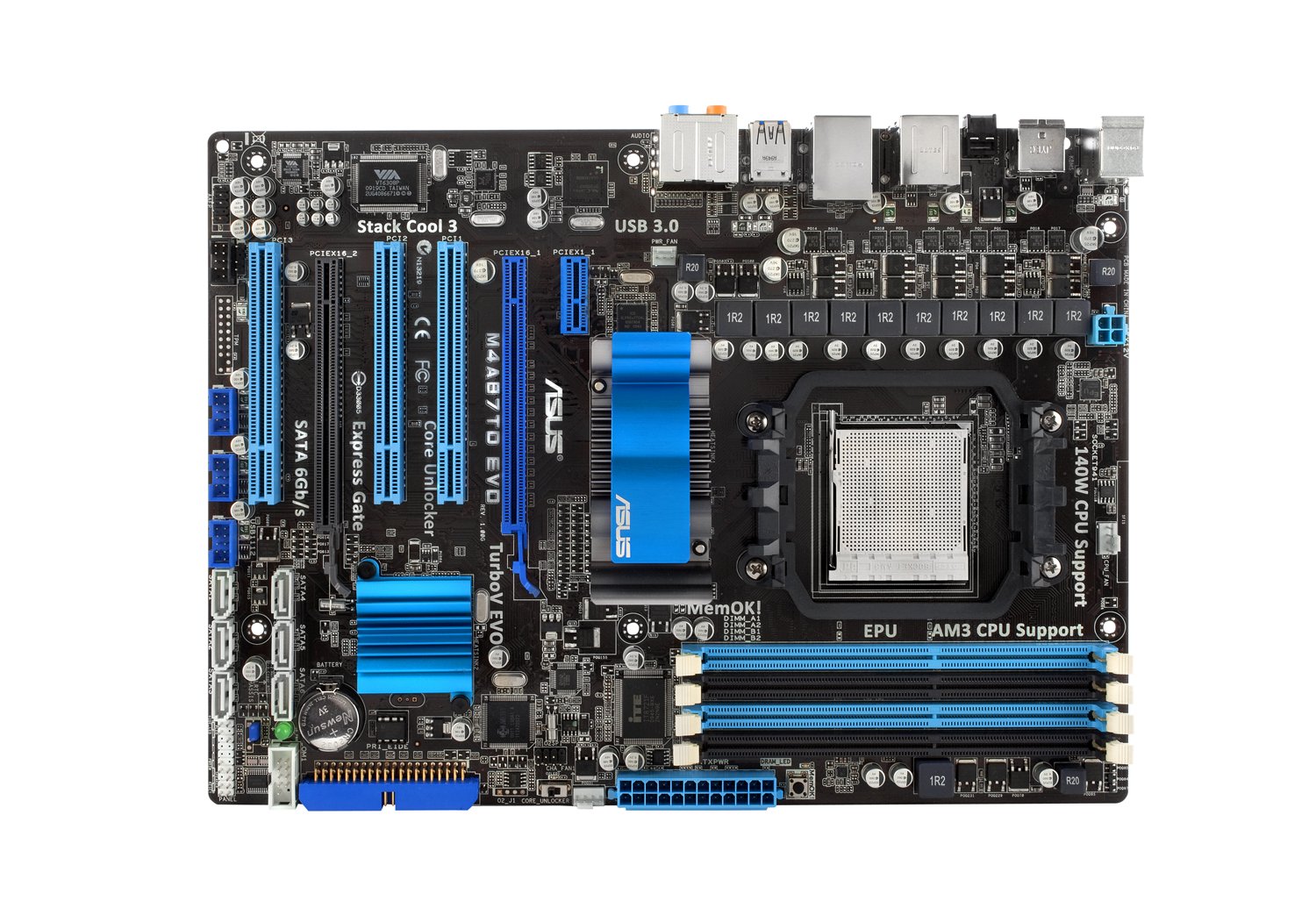
Figure 1: Full view of the ASUS M4A87TD EVO Motherboard, highlighting various components and connectors.
2.2 CPU Installation
The motherboard features an AM3 socket for compatible AMD processors. Ensure the CPU is correctly oriented before placing it into the socket.
- Locate the CPU socket on the motherboard.
- Lift the load lever on the side of the socket.
- Align the triangular mark on the CPU with the corresponding mark on the socket.
- Gently place the CPU into the socket without forcing it.
- Lower the load lever to secure the CPU in place.
Figure 2: Detailed view of the AM3 CPU socket area on the motherboard.
2.3 Memory (RAM) Installation
The motherboard supports up to 16GB of DDR3 memory across four DIMM slots. For dual-channel operation, install memory modules in matched pairs.
- Open the clips at both ends of the DIMM slot.
- Align the notch on the memory module with the key in the DIMM slot.
- Press down firmly on both ends of the memory module until the clips snap into place.
Figure 3: View of the four DDR3 DIMM slots for memory installation.
2.4 Expansion Card Installation
The motherboard includes two PCI-Express 2.0 x16 slots (supporting ATI CrossFireX), one PCI-Express 2.0 x1 slot, and three PCI slots.
- Select an appropriate expansion slot for your card (e.g., graphics card in a PCIe x16 slot).
- Remove the corresponding slot cover from your computer case.
- Align the card with the slot and press down firmly until it is seated.
- Secure the card with a screw to the case.
Figure 4: Expansion slots including PCI-Express x16, x1, and standard PCI slots.
2.5 Storage Device Connection
Connect SATA 6Gb/s (SATA3) and SATA 3Gb/s (SATA2) devices to the available ports.
- Identify the SATA 6Gb/s ports (typically labeled SATA6G_1, SATA6G_2) and SATA 3Gb/s ports.
- Connect one end of the SATA data cable to the motherboard port and the other end to your storage device (HDD/SSD).
- Ensure the storage device also receives power from the power supply unit.
Figure 5: SATA 6Gb/s and SATA 3Gb/s ports for connecting storage devices.
2.6 Power Connections
Connect the main 24-pin ATX power connector and the 4-pin ATX 12V power connector from your power supply unit to the motherboard.
- 24-pin ATX Power Connector: Provides main power to the motherboard.
- 4-pin ATX 12V Power Connector: Provides additional power to the CPU.
2.7 Rear I/O Panel Connections
Connect peripheral devices to the rear input/output ports.
- PS/2 Ports: For keyboard and mouse.
- USB 2.0/3.0 Ports: For various USB devices.
- eSATA2 Port: For external SATA devices.
- IEEE 1394 Ports: For FireWire devices.
- RJ45 LAN Port: For network connection.
- Audio I/O Jacks: For speakers, microphone, and other audio devices.
- Optical S/PDIF Out: For digital audio output.
Figure 6: Rear I/O panel showing various connectivity options including USB 3.0, LAN, and audio ports.
3. Operating Instructions
After successful hardware installation, proceed with system startup and software configuration.
3.1 Initial Power On and BIOS Setup
- Connect your monitor, keyboard, and mouse.
- Power on your computer.
- Press the DEL key during startup to enter the BIOS setup utility.
- Configure essential settings such as boot order, date, and time.
- Explore advanced features like Core Unlocker and TurboV EVO for performance tuning, if desired. Refer to the BIOS utility for detailed explanations of each setting.
- Save changes and exit the BIOS.
3.2 Operating System Installation
Install your preferred operating system (e.g., Windows 10) from a bootable USB drive or optical disc.
3.3 Driver Installation
Install the necessary drivers for the motherboard components, including chipset, LAN, audio, and USB 3.0 drivers. These are typically provided on a support DVD or available for download from the ASUS website.
4. Maintenance
Regular maintenance helps ensure the longevity and stability of your motherboard.
- Dust Removal: Periodically clean dust from the motherboard and components using compressed air. Ensure the system is powered off and unplugged before cleaning.
- BIOS Updates: Check the ASUS support website for the latest BIOS updates. Updating the BIOS can improve compatibility and system stability. Follow the instructions provided by ASUS carefully during the update process.
- Component Checks: Ensure all cables and components are securely seated. Loose connections can lead to intermittent issues.
5. Troubleshooting
This section addresses common issues you might encounter.
- System Does Not Power On:
- Verify all power supply connections to the motherboard (24-pin ATX and 4-pin ATX 12V).
- Ensure the power supply unit is switched on.
- Check front panel power switch connections to the motherboard.
- No Display Output:
- Ensure the graphics card is properly seated in its PCIe slot and has adequate power.
- Check monitor connections and ensure the monitor is powered on and set to the correct input.
- If using integrated graphics (if available on your CPU/APU, though this board requires a discrete GPU), ensure the display cable is connected to the motherboard's video output.
- Memory (RAM) Issues:
- The motherboard features a DRAM LED that illuminates if there is an issue with memory detection.
- Reseat memory modules firmly in their slots.
- Test with one memory module at a time to identify a faulty stick or slot.
- Operating System Instability:
- Ensure all drivers are correctly installed and up to date.
- Check for overheating issues by monitoring CPU and chipset temperatures.
- Run memory diagnostic tools to check for RAM errors.
- USB Ports Remain Powered After Shutdown:
- This is a known characteristic for some configurations. To fully power off USB devices, either toggle the power supply switch off and on, or unplug and replug the power cable from the wall.
6. Specifications
| Feature | Detail |
|---|---|
| Brand | ASUS |
| Model Number | M4A87TD EVO |
| CPU Socket | Socket AM3 |
| Compatible Processors | AMD Phenom II / Athlon II / Sempron 100 Series |
| Chipset Type | AMD 870 & SB850 |
| RAM Memory Technology | DDR3 2000(O.C.)/1600/1333/1066 |
| Memory Slots Available | 4 (Dual Channel, ECC/Non-ECC Un-buffered) |
| RAM Memory Maximum Size | 16 GB |
| Graphics Card Interface | PCI, PCI Express (2x PCIe 2.0 x16, 1x PCIe 2.0 x1, 3x PCI) |
| System Bus Standard Supported | SATA 6Gb/s (SATA 3) |
| Total SATA Ports | 7 (6x SATA 6Gb/s, 1x eSATA2) |
| USB Ports | 12x USB 2.0 (6 rear, 6 by headers), 2x USB 3.0 (rear) |
| Number of Ethernet Ports | 1 (RTL8111E Gigabit LAN) |
| Audio | 8-Channel HD Audio, Optical S/PDIF Out |
| Power Connector | 1x 24-pin ATX, 1x 4-pin ATX 12V |
| Platform | Windows 10 (Compatible) |
| Item Weight | 2.9 pounds |
7. Warranty Information
The ASUS M4A87TD EVO motherboard comes with a 3-year warranty. For specific terms and conditions, please refer to the warranty card included with your product or visit the official ASUS support website.
8. Support
For technical assistance, driver downloads, or further information, please visit the official ASUS support website. You can typically find support resources by searching for your product model, M4A87TD EVO, on the ASUS website.
ASUS Official Website: https://www.asus.com/support/


