
1. Introduction
This manual provides essential information for the installation, operation, and maintenance of your Faria Dress White 4" Tachometer, Model 33104. Designed for gas engines, specifically all outboards, this instrument accurately measures engine revolutions per minute (RPM) up to 7,000 RPM, ensuring optimal engine performance and monitoring.
Key features include:
- Made in USA, ensuring quality craftsmanship.
- CE Certified for compliance with European safety standards.
- Designed for easy installation in standard 2" and 4" gauge mounting holes.
- Provides accurate RPM readings for gas outboard engines.
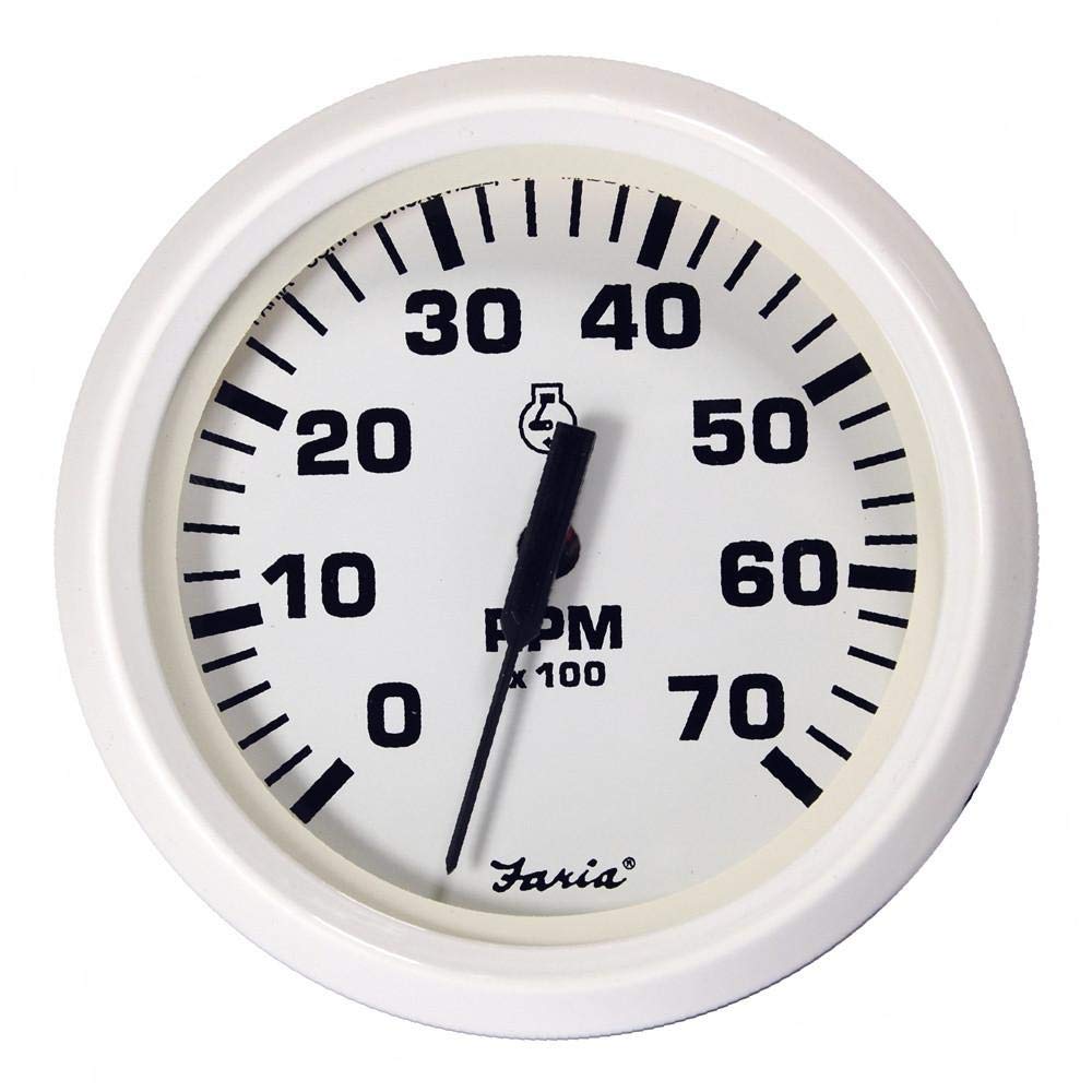
Figure 1: The Faria Dress White 4" Tachometer. This image shows the front view of the tachometer with a white bezel, white dial, black numbers (0-70), and a black needle. The dial indicates "RPM x 100" and features the Faria logo.
2. Setup and Installation
Proper installation is crucial for accurate operation and longevity of your tachometer. This unit is designed for easy installation into standard 2" and 4" gauge mounting holes.
2.1 Tools Required
- Drill (if new mounting hole is required)
- Hole Saw (appropriate size for 4" gauge)
- Screwdriver
- Wire Strippers/Crimpers
- Electrical Tape or Heat Shrink Tubing
- Marine-grade electrical connectors
2.2 Mounting Instructions
- Select Location: Choose a flat, secure surface on your dashboard or panel that is easily visible to the operator and away from direct spray or excessive vibration.
- Cut Mounting Hole: If a new hole is needed, use a hole saw to cut a 4" diameter hole. Ensure there is sufficient clearance behind the panel for the gauge body and wiring.
- Insert Gauge: Carefully insert the tachometer into the mounting hole from the front of the panel.
- Secure Gauge: Attach the supplied mounting bracket and nuts to the back of the gauge, tightening them securely but without overtightening to avoid damage.
2.3 Wiring Diagram (General)
While specific wiring may vary by engine and boat model, a typical tachometer connection involves four wires:
- Red Wire: Connect to a switched 12V DC positive (+) power source (e.g., ignition switch).
- Black Wire: Connect to a reliable ground (-) connection.
- Green/Blue Wire (Signal): Connect to the engine's tachometer signal output. This is typically found on the alternator's "AC tap" or the ignition coil's negative terminal, depending on the engine type. Consult your engine's service manual for the exact signal wire location.
- White/Blue Wire (Illumination): Connect to the boat's navigation light circuit or another switched 12V DC source for dial illumination.
Ensure all connections are secure, insulated, and protected from moisture. Incorrect wiring can damage the instrument or electrical system.
2.4 Calibration
Many tachometers require calibration to match the number of poles on your engine's alternator or the number of ignition pulses per revolution. This tachometer may have a selector switch or dip switches on the back for setting the correct engine type (e.g., 4-stroke, 2-stroke, number of cylinders). Refer to the specific instructions provided with the physical product for detailed calibration steps, as this is critical for accurate RPM readings.
3. Operating Instructions
Once properly installed and calibrated, operating your Faria tachometer is straightforward.
- Power On: Turn on your boat's ignition. The tachometer needle should briefly sweep and then settle at zero RPM. If connected, the dial illumination will activate with your navigation lights.
- Engine Start: Start your outboard engine. As the engine runs, the tachometer needle will indicate the current engine RPM.
- Monitoring RPM: Observe the tachometer during engine operation. The dial displays RPM in hundreds (e.g., '30' on the dial means 3000 RPM). Maintain RPM within the manufacturer's recommended operating range for your specific engine to ensure longevity and efficiency.
- Engine Shutdown: When the engine is turned off, the tachometer needle will return to zero.
Important: Always refer to your engine's owner's manual for recommended idle speeds, maximum RPM, and other critical operating parameters.
4. Maintenance
Your Faria tachometer is designed for durability in marine environments. Minimal maintenance is required to ensure its continued accuracy and appearance.
- Cleaning: Clean the gauge face and bezel with a soft, damp cloth. Avoid abrasive cleaners or solvents, which can damage the finish or clear lens.
- Connections: Periodically inspect all electrical connections for corrosion, looseness, or damage. Ensure connections are clean and tight to prevent intermittent readings or failure.
- Moisture Protection: While the gauge is designed for marine use, ensure the rear connections are protected from excessive moisture or spray, especially in open cockpits.
5. Troubleshooting
If you experience issues with your tachometer, consult the following troubleshooting guide before seeking professional assistance.
| Problem | Possible Cause | Solution |
|---|---|---|
| No Reading / Gauge Dead | No power to the gauge; faulty ground connection; blown fuse. | Check 12V power supply (red wire) and ground connection (black wire). Inspect inline fuse if present. |
| Inaccurate Reading | Incorrect calibration setting; poor signal connection; engine issue. | Verify calibration settings (e.g., pole switch) match your engine. Check signal wire connection (green/blue). Ensure engine is running smoothly. |
| Intermittent Reading | Loose or corroded electrical connections; faulty signal wire. | Inspect all wiring connections for tightness and corrosion. Repair or replace damaged wires. |
| No Illumination | No power to illumination wire; faulty bulb/LED. | Check 12V power supply to illumination wire (white/blue). Verify navigation lights are on. |
If problems persist after attempting these solutions, contact Faria customer support or a qualified marine technician.
6. Specifications
| Feature | Detail |
|---|---|
| Model Number | 33104 |
| Brand | Faria |
| Gauge Type | Tachometer |
| RPM Range | 0 - 7,000 RPM |
| Engine Compatibility | Gas - All Outboards |
| Mounting Hole Size | Standard 4 inch |
| Certifications | CE Certified |
| Country of Origin | USA |
| Item Package Dimensions | 12 x 12 x 12 inches |
| Package Weight | 16 ounces |
| UPC | 766129019612 |
7. Warranty and Support
Faria Beede Instruments stands behind the quality of its products. For specific warranty details, please refer to the warranty card included with your product or visit the official Faria Beede Instruments website. Keep your proof of purchase for warranty claims.
For technical support, troubleshooting assistance beyond this manual, or to inquire about replacement parts, please contact Faria Beede Instruments customer service. Contact information can typically be found on their official website or product packaging.
Manufacturer: Faria Beede Instruments
Website: www.fariabeede.com

