
1. Introduction
Thank you for choosing the EXTEL WEMR 83002 Digital Multimeter. This device is designed for precise electrical measurements, featuring a clear 15mm display for easy reading. This manual provides essential information for safe and effective operation of your multimeter.
2. Safety Instructions
Always observe the following safety precautions to prevent electric shock or damage to the meter:
- Read all instructions carefully before use.
- Do not apply voltage or current that exceeds the maximum rated input for any range.
- Use extreme caution when working with voltages above 60V DC or 30V AC RMS.
- Always disconnect the test leads from the circuit before changing functions.
- Ensure the battery cover is securely closed before operation.
- Do not operate the meter if it appears damaged or if the casing is open.
3. Product Features
The EXTEL WEMR 83002 Digital Multimeter offers a range of functionalities for various electrical testing needs:
- 15mm Digital Display: Provides clear and precise measurement readings.
- AC Voltage Measurement: Ranges include 200 V and 600 V.
- DC Voltage Measurement: Ranges include 200mV, 2 V, 20 V, 200 V, and 600 V.
- DC Current Measurement: Ranges include 200 µA, 2 mA, 20 mA, 200 mA, and 10 A.
- Resistance Measurement: Ranges include 2 kOhms, 20 kOhms, 200 kOhms, and 2 MOhms.
- hFE Test: For NPN and PNP transistors.
- Diode Test: For semiconductor measurement.
- Shockproof Casing: Designed for durability and protection.
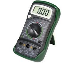
Image showing the EXTEL WEMR 83002 Digital Multimeter, featuring its display and rotary dial.
4. Setup
4.1. Battery Installation
- Ensure the multimeter is turned off.
- Locate the battery compartment cover on the back of the unit.
- Unscrew the retaining screw(s) and remove the cover.
- Insert a new 9V battery, observing the correct polarity (+ and -).
- Replace the battery cover and secure it with the screw(s).
4.2. Connecting Test Leads
- Insert the black test lead into the "COM" (common) jack.
- For voltage, resistance, and diode measurements, insert the red test lead into the "VΩmA" jack.
- For current measurements (up to 10A), insert the red test lead into the "10A" jack.
5. Operating Instructions
5.1. Measuring DC Voltage
- Set the rotary switch to the desired "VDC" range (e.g., 20V for measuring up to 20V).
- Connect the red test lead to the positive (+) side of the circuit and the black test lead to the negative (-) side.
- Read the voltage value on the display.
5.2. Measuring AC Voltage
- Set the rotary switch to the desired "VAC" range (e.g., 200V or 600V).
- Connect the test leads across the AC voltage source.
- Read the voltage value on the display.
5.3. Measuring DC Current
- Set the rotary switch to the desired "ADC" range (e.g., 200mA).
- Important: For current measurements, the multimeter must be connected in series with the circuit.
- Open the circuit where current is to be measured.
- Connect the red test lead to the higher potential side and the black test lead to the lower potential side of the break.
- Read the current value on the display.
5.4. Measuring Resistance
- Ensure the circuit is de-energized before measuring resistance.
- Set the rotary switch to the desired "Ω" (Ohms) range.
- Connect the test leads across the component to be measured.
- Read the resistance value on the display.
5.5. Diode Test
- Set the rotary switch to the "Diode" symbol.
- Connect the red test lead to the anode and the black test lead to the cathode of the diode.
- The display will show the forward voltage drop. Reverse the leads; the display should show "OL" (Open Loop) for a good diode.
5.6. hFE Test (Transistor Test)
- Set the rotary switch to the "hFE" position.
- Identify if the transistor is NPN or PNP.
- Insert the transistor leads (Emitter, Base, Collector) into the corresponding sockets in the hFE test socket.
- Read the hFE value on the display.
6. Maintenance
6.1. Cleaning
Wipe the meter with a dry, soft cloth. Do not use abrasives or solvents.
6.2. Battery Replacement
When the battery low indicator appears on the display, replace the 9V battery as described in the "Battery Installation" section (4.1). Remove the battery if the meter is not used for extended periods.
6.3. Fuse Replacement
If the current measurement function fails, the fuse may need replacement. Refer to the specifications for the correct fuse type. Fuse replacement should only be performed by qualified personnel.
7. Troubleshooting
| Problem | Possible Cause | Solution |
|---|---|---|
| No display or dim display | Low battery or no battery installed. | Replace the 9V battery. |
| "OL" or "1" displayed | Overload, open circuit, or incorrect range. | Select a higher range, check circuit continuity, or ensure leads are properly connected. |
| Incorrect current reading | Blown fuse or incorrect lead connection. | Check and replace fuse if necessary. Ensure leads are in the correct current jacks and connected in series. |
| No reading for resistance | Circuit is energized or component is open. | Ensure circuit is de-energized. Check component for breaks. |
8. Specifications
- Model: WEMR 83002
- Brand: EXTEL
- Display: 15mm Digital LCD
- Power Source: 9V Battery (battery powered)
- AC Voltage Ranges: 200V, 600V
- DC Voltage Ranges: 200mV, 2V, 20V, 200V, 600V
- DC Current Ranges: 200µA, 2mA, 20mA, 200mA, 10A
- Resistance Ranges: 2kΩ, 20kΩ, 200kΩ, 2MΩ
- Special Functions: hFE (NPN/PNP Transistor Test), Diode Test
- Casing: Shockproof
- Date First Available: September 1, 2009
9. Warranty and Support
EXTEL products are manufactured to high-quality standards. For specific warranty information, please refer to the warranty card included with your purchase or contact EXTEL customer support. Information regarding spare parts availability is currently unavailable.
For technical assistance or support, please visit the official EXTEL website or contact their customer service department.