
MSI X58 Pro
MSI X58 Pro Motherboard User Manual
Model: X58 Pro | Brand: MSI
Introduction
This user manual provides comprehensive instructions for the installation, operation, and maintenance of your MSI X58 Pro motherboard. Designed for Intel Core i7 processors, this ATX form factor motherboard offers robust performance and extensive connectivity options for building a high-performance computing system.
Key Features
- Supports Intel Core i7 processors in LGA1366 package.
- Intel X58 and ICH10R Chipsets for high performance and extensive I/O.
- Six DDR3 DIMM slots supporting up to 24GB of unbuffered DDR3 800/1066/1333 SDRAM in triple channel mode.
- Three PCI Express Gen2 x16 slots with support for ATI CrossFireX technology.
- Integrated Realtek ALC888S 8-channel audio codec.
- Realtek 8111C Gigabit LAN for high-speed network connectivity.
- Multiple storage options including 6 SATAII ports (ICH10R), 1 SATAII port (JMicron 363), 1 eSATA port, and 1 ATA133 connector.
- IEEE 1394 FireWire support with two ports.
- Extensive USB 2.0 connectivity with up to 12 ports.
Setup Guide
1. Before You Begin
Before installing any components, ensure you are working in a static-free environment. Use an anti-static wrist strap and mat to prevent damage to sensitive electronic components. Verify that all components, including CPU, RAM, and power supply, are compatible with the MSI X58 Pro motherboard.
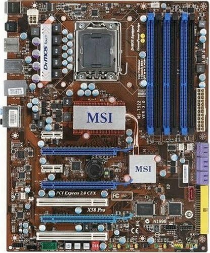
Figure 1: Overview of the MSI X58 Pro Motherboard. This image displays the full layout of the motherboard, including the CPU socket, DIMM slots, PCI Express slots, and various connectors.
2. Component Installation
2.1. CPU Installation
Carefully open the LGA1366 CPU socket lever. Align the triangular mark on the Intel Core i7 processor with the corresponding mark on the socket. Gently place the CPU into the socket without forcing it. Close the lever to secure the CPU. Apply thermal paste and install the CPU cooler according to its manufacturer's instructions.
2.2. Memory Installation
The MSI X58 Pro features six DDR3 DIMM slots. For optimal performance, install memory modules in a triple-channel configuration. Refer to the motherboard manual for specific slot population order. Open the clips on both ends of the DIMM slot, align the memory module with the notch, and press firmly until the clips snap into place.

Figure 2: Close-up of the CPU Socket and Memory Slots. This view highlights the LGA1366 CPU socket and the six DDR3 DIMM slots, crucial for proper CPU and RAM installation.
2.3. Expansion Card Installation
Install graphics cards into the PCI Express Gen2 x16 slots. For ATI CrossFireX configurations, utilize multiple x16 slots as required. Other expansion cards (e.g., sound cards, network cards) can be installed in the PCI Express x1 or standard PCI slots. Ensure cards are fully seated and secured with a screw to the chassis.
2.4. Storage Device Connection
Connect SATAII hard drives or SSDs to the available SATAII ports. The motherboard supports up to six SATAII devices via the ICH10R chipset and an additional SATAII port via the JMicron 363. An ATA133 connector is available for older IDE devices. For external storage, an eSATA port is provided on the back panel.
2.5. Power Supply Connection
Connect the 24-pin ATX main power connector and the 8-pin ATX 12V CPU power connector from your power supply unit to the corresponding ports on the motherboard. Ensure all power connections are secure to prevent system instability.
3. Initial Boot and BIOS Configuration
After all components are installed and connected, power on your system. Press the DEL key during startup to enter the BIOS setup utility. Configure essential settings such as boot order, date/time, and enable/disable integrated peripherals as needed. Save changes and exit BIOS to proceed with operating system installation.
Operating Instructions
1. Driver Installation
After installing your operating system, install the necessary drivers for the motherboard's components. This includes chipset drivers, audio drivers (Realtek ALC888S), LAN drivers (Realtek 8111C), and any other specific drivers for integrated peripherals. Drivers are typically provided on a support CD or can be downloaded from the MSI official website.
2. Software Utilities
MSI may provide various software utilities to enhance system performance, monitoring, and customization. These utilities can include tools for system information, fan control, and BIOS updates. Refer to the MSI website for available software for your X58 Pro model.
3. BIOS/UEFI Navigation
The BIOS interface allows for advanced configuration of your motherboard. Use the arrow keys to navigate through menus, Enter to select options, and Esc to go back. Detailed explanations for each setting can be found within the BIOS itself or in the comprehensive manual available on the MSI support page.

Figure 3: Rear I/O Panel and Expansion Slots. This image provides a clear view of the various ports available on the back of the motherboard, including USB, LAN, audio jacks, and the expansion slots for add-in cards.
Maintenance
- Dust Cleaning: Regularly clean dust from the motherboard and components using compressed air. Pay special attention to heatsinks (chipset, CPU) and fan blades to ensure optimal cooling.
- Connection Checks: Periodically check all cable connections (power, data, front panel) to ensure they are securely seated.
- BIOS Updates: Check the MSI website for the latest BIOS updates. BIOS updates can improve compatibility, stability, and performance. Follow MSI's instructions carefully when updating the BIOS to avoid system damage.
- Thermal Paste: If experiencing high temperatures, especially around the chipset heatsinks, consider reapplying thermal paste. Some users have reported improved thermal performance by reseating the chipset heatsink with fresh thermal compound.
Troubleshooting
- No Power/No Boot:
- Ensure all power cables (24-pin ATX, 8-pin ATX 12V) are firmly connected.
- Check front panel connections (Power SW, Reset SW).
- Test with minimal components (CPU, one RAM stick, graphics card) to isolate the issue.
- Memory Issues (e.g., not recognizing full RAM, crashes):
- Verify RAM modules are fully seated in their slots.
- Ensure RAM is compatible with the motherboard (DDR3 800/1066/1333).
- Test each RAM stick individually in different slots.
- Check BIOS settings for memory frequency and voltage.
- Overheating (especially IOH/Northbridge):
- Ensure proper airflow within the PC case.
- Verify CPU and chipset heatsinks are securely mounted and fans are operating.
- Consider reapplying thermal paste to the chipset heatsink if temperatures are consistently high (e.g., above 70°C at idle).
- Add case fans or a spot-cooling fan directed at the chipset heatsink if necessary.
- Peripheral Not Detected:
- Ensure the device is properly connected.
- Install or update relevant drivers.
- Check BIOS settings to ensure the port/controller is enabled.

Figure 4: Chipset Heatsinks and Power Delivery Area. This image focuses on the heatsinks covering the Intel X58 and ICH10R chipsets, as well as the power delivery components, which are critical for system stability and thermal management.
Technical Specifications
| Category | Specification |
|---|---|
| Form Factor | ATX (12.0 in. x 9.6 in.) |
| CPU Support | Intel Core i7 processors (LGA1366 socket) |
| Chipset | Intel X58, Intel ICH10R |
| Main Memory | 6 x DDR3 DIMM slots, Triple Channel, up to 24GB, DDR3 800/1066/1333 SDRAM |
| Expansion Slots | 3 x PCI Express Gen2 x16 (supports ATI CrossFireX), 2 x PCI Express Gen2 x1, 2 x PCI |
| IDE Controller | 1 x Ultra DMA 66/100/133 (JMicron 363) |
| SATA Controller | 6 x SATAII (ICH10R, RAID 0/1/5/10, AHCI), 1 x SATAII (JMicron 363), 1 x eSATA (JMicron 363) |
| Audio | Realtek ALC888S 8-channel HD Audio |
| LAN | Realtek 8111C Gigabit LAN (10/100/1000) |
| IEEE 1394 | JMicron 381 (2 ports, 400Mbps) |
| USB Ports | Up to 12 x USB 2.0 ports (6 rear, 6 via internal headers) |
| Internal I/O Connectors | 24-pin ATX, 8-pin ATX 12V, 5 x FAN, CD-in, Front panel audio, Front panel, Chassis intrusion, Serial port, 3 x USB 2.0 headers, 7 x SATAII, 1 x ATA133, 1 x IEEE1394 header, Reset Button, Power Button, SPDIF-out, D-LED2, TPM module |
| Back Panel I/O Ports | Clear CMOS button, PS/2 Keyboard, PS/2 Mouse, eSATA, IEEE1394, 6 x USB 2.0, RJ45 LAN, 6-in-1 audio jack, Optical SPDIF-out |
Warranty Information
MSI products are covered by a limited warranty. The specific terms and duration of the warranty may vary by region and product type. Please refer to the warranty card included with your product or visit the official MSI website for detailed warranty information and registration procedures. Keep your proof of purchase for warranty claims.
Support
For technical assistance, driver downloads, BIOS updates, and frequently asked questions, please visit the official MSI support website. You can also contact MSI customer service directly through the contact information provided on their website. When contacting support, please have your motherboard model (X58 Pro) and serial number ready.
MSI Official Website: www.msi.com
Related documentsX58 Pro


Ask a question about this manual
Ask about setup, troubleshooting, compatibility, parts, safety, or missing instructions. Manuals+ will review the question and use this page’s manual context to help answer it.