1. Introduction
This manual provides essential information for the safe and effective operation, maintenance, and troubleshooting of your RIDGID 41935 Model 700 Hand-Held 120-Volt Power Drive Pipe Threader. Please read this manual thoroughly before using the tool to ensure proper handling and to prevent injury or damage.

Image 1.1: The RIDGID Model 700 Hand-Held Power Drive Pipe Threader. This image displays the main unit of the power drive, highlighting its compact design and robust construction, ready for pipe threading applications.
The RIDGID Model 700 is a heavy-duty, hand-held power drive designed for demanding pipe and conduit threading applications. It is capable of cutting both right and left-hand threads and can also serve as a power source for RIDGID 258 and 258XL Power Pipe Cutters. Its durable cast aluminum housing and heavy-duty switch ensure reliability and a long service life.
2. Safety Information
Always prioritize safety when operating power tools. Failure to follow safety instructions can result in serious injury or property damage.
General Safety Precautions:
- Read All Instructions: Understand all warnings and operating instructions before use.
- Wear Personal Protective Equipment (PPE): Always wear safety glasses, hearing protection, and appropriate work gloves.
- Secure Workpiece: Ensure the pipe or conduit is securely clamped in a vise or stand to prevent rotation during threading.
- Maintain a Clean Work Area: Keep the work area well-lit and free of clutter to prevent accidents.
- Avoid Hazardous Environments: Do not operate the tool in damp or wet locations, or in the presence of flammable liquids or gases.
- Use Proper Voltage: Ensure the power supply matches the tool's specified voltage (120-Volt).
- Unplug When Not in Use: Disconnect the tool from the power source before making adjustments, changing accessories, or servicing.
- Keep Hands Clear: Never place hands near moving parts, especially the die head during operation.
- Use Correct Accessories: Only use RIDGID 12-R, 00-R, 00-RB, and 11-R Die Heads with appropriate adapters.
3. Components and Package Contents
The RIDGID Model 700 Hand-Held Power Drive typically includes the following items:
- RIDGID Model 700 Power Drive Unit
- Torque Arm
- Operator's Manual (this document)
- 14" Pipe Wrench (may vary by package)

Image 3.1: Package contents for the RIDGID Model 700. This image illustrates the main power drive unit along with a 14-inch pipe wrench, an operator's manual, and a torque arm, which are typically included.
4. Setup
Proper setup is crucial for safe and efficient operation.
4.1 Attaching the Die Head
- Ensure the power drive is unplugged.
- Select the appropriate RIDGID die head (e.g., 12-R, 00-R, 00-RB, 11-R) for the pipe size and thread type.
- Align the die head with the drive shaft of the Model 700.
- Push the die head onto the shaft and rotate slightly until it locks into place. Ensure it is securely seated.

Image 4.1: Close-up view of a die head being attached to the RIDGID Model 700. This image demonstrates the correct alignment and attachment of a die head to the power drive unit.
4.2 Securing the Workpiece
The pipe or conduit must be held firmly to prevent it from rotating with the die head.
- Use a sturdy pipe vise or a RIDGID Tri-Stand Chain Vise to secure the pipe.
- Ensure the pipe is level and positioned correctly for threading.
- Attach the torque arm to the Model 700 and brace it against the pipe vise or a stable surface to counteract the rotational force of the tool.

Image 4.2: The RIDGID Model 700 in use, threading a pipe secured in a vise. This image shows the power drive attached to a pipe, which is firmly held in a red pipe vise, illustrating proper workpiece securing.
5. Operating Instructions
Follow these steps for effective pipe threading.
5.1 Threading a Pipe
- After securing the pipe and attaching the die head and torque arm, plug the power drive into a 120-Volt power outlet.
- Position the die head squarely onto the end of the pipe.
- Press the trigger switch to start the motor. The die head will begin to rotate.
- Apply steady, firm pressure to engage the dies with the pipe.
- As the threads begin to form, apply cutting oil generously to the dies and the pipe. Continuous lubrication is essential for clean threads and to extend die life.
- Continue threading until the desired thread length is achieved. The Model 700 can cut both right and left-hand threads.
- Release the trigger switch to stop the motor.
- Reverse the rotation (if applicable) to back the die head off the newly cut threads.
- Inspect the threads for quality and cleanliness.

Image 5.1: A close-up of the RIDGID Model 700 die head engaging a pipe. This image highlights the precision of the tool as it cuts threads, emphasizing the importance of proper technique and lubrication.
5.2 Using with Power Pipe Cutters
The Model 700 can power RIDGID 258 and 258XL Power Pipe Cutters. Refer to the specific instruction manual for the power pipe cutter for detailed operating procedures when used in conjunction with the Model 700.
6. Maintenance
Regular maintenance ensures optimal performance and extends the life of your tool.
6.1 Cleaning
- After each use, unplug the tool and clean any metal shavings or debris from the die head and the power drive unit.
- Use a brush or compressed air to remove debris. Avoid using solvents that may damage plastic components.
6.2 Lubrication
- Ensure adequate cutting oil is used during threading operations. This lubricates the dies and cools the pipe, preventing premature wear.
- Periodically check the motor's ventilation openings and keep them clear of obstructions to ensure proper cooling.
6.3 Inspection
- Regularly inspect the power cord for damage. Replace immediately if frayed or cut.
- Check the die heads for wear or damage. Worn dies will produce poor quality threads and should be replaced.
- Ensure all fasteners are tight.
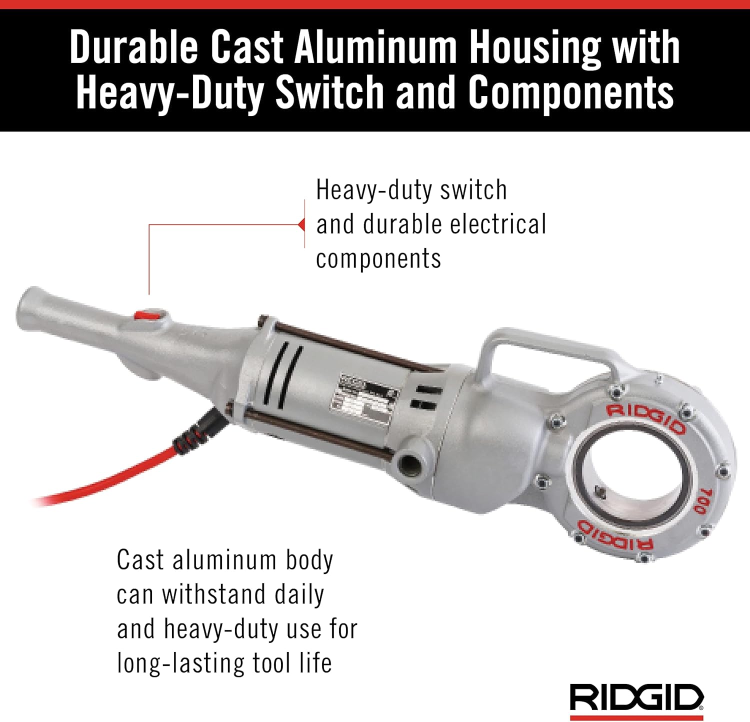
Image 6.1: Detailed view of the RIDGID Model 700's durable cast aluminum housing and heavy-duty switch. This image highlights the robust construction designed for longevity and ease of maintenance.
7. Troubleshooting
This section addresses common issues you might encounter.
| Problem | Possible Cause | Solution |
|---|---|---|
| Tool does not start | No power supply Damaged power cord Faulty switch | Check power connection and outlet Inspect and replace damaged cord Contact authorized service center |
| Poor thread quality | Worn or dull dies Insufficient lubrication Improper die head alignment Incorrect pipe material/size | Replace dies Apply ample cutting oil Ensure die head is properly seated Verify pipe compatibility with dies |
| Tool stalls during threading | Excessive pressure Dull dies Lack of lubrication Pipe not securely held | Reduce pressure Replace dies Apply cutting oil Re-secure pipe in vise |
| Excessive vibration or noise | Loose components Damaged internal parts | Check and tighten fasteners Contact authorized service center |
8. Specifications
Key technical specifications for the RIDGID 41935 Model 700 Hand-Held Power Drive.
- Model Number: 41935
- Voltage: 115 Volts
- Power Source: Corded Electric
- Wattage: 375W
- Pipe Capacity: 1/8 inch to 2 inches (6mm - 50mm)
- Bolt Thread Capacity: 1/4 inch to 1 inch (8mm - 25mm) (using 00-RB die heads)
- Compatible Die Heads: RIDGID 12-R, 00-R, 00-RB, and 11-R (with adapters)
- Item Weight: Approximately 24.2 pounds (11 Kilograms)
- Product Dimensions: 32 x 9 x 31 inches
- Housing Material: Cast Aluminum
- Special Feature: Portable

Image 8.1: Visual representation of the RIDGID Model 700's pipe and bolt thread capacities. This graphic clearly shows the supported pipe diameters from 1/8-inch to 2-inch and bolt threads from 1/4-inch to 1-inch.
9. Warranty
RIDGID stands behind the quality of its products.
RIDGID covers its products with a lifetime warranty against defects in material or workmanship for the life of the tool. For specific details and to register your product, please visit the official RIDGID website or contact customer support.

Image 9.1: A badge indicating RIDGID's Full Lifetime Warranty against material defects and workmanship. This image reinforces the manufacturer's commitment to product quality and customer assurance.
10. Support
For further assistance, technical support, or to inquire about service and parts, please contact RIDGID customer service or visit their official website.
RIDGID Official Website: www.ridgid.com
You can also find additional resources and product information on the RIDGID Store on Amazon.