
Introduction
This manual provides detailed instructions for the installation, operation, and maintenance of the MSI K9A2 CF-F V2 ATX motherboard. Please read this manual thoroughly before proceeding with installation to ensure proper setup and functionality. This motherboard supports AMD Socket AM2+ processors and DDR2 memory.
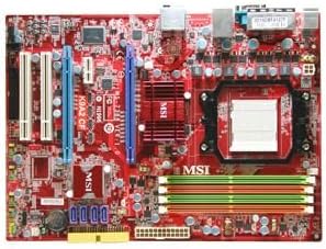
Image: Top-down view of the MSI K9A2 CF-F V2 motherboard, showcasing its various components including the CPU socket, RAM slots, PCI-E slots, and chipset heatsinks.
1. Setup and Installation
Follow these steps carefully to install your motherboard and its components.
1.1 CPU Installation
- Prepare the CPU Socket: Gently lift the load lever on the Socket AM2+ CPU socket.
- Align the CPU: Carefully align the CPU with the socket, ensuring the golden triangle on the CPU matches the triangle on the socket. Do not force the CPU into the socket.
- Secure the CPU: Once the CPU is seated correctly, lower the load lever to secure it in place.
- Install CPU Cooler: Apply thermal paste (if not pre-applied) and install the CPU cooler according to its manufacturer's instructions. Ensure it is securely fastened.
1.2 RAM Installation
- Open DIMM Slot Clips: Push open the clips at both ends of the DDR2 DIMM slots.
- Align RAM Module: Align the notch on the RAM module with the key in the DIMM slot.
- Insert RAM: Press down firmly on both ends of the RAM module until the clips snap into place.
- Dual Channel Configuration: For optimal performance, install RAM modules in matching colored slots for dual-channel operation. Refer to the motherboard diagram for specific slot pairings.
1.3 Graphics Card Installation
- Locate PCI-E x16 Slot: Identify the primary PCI-E x16 slot on the motherboard.
- Open Retention Clip: Gently push open the retention clip at the end of the PCI-E slot.
- Insert Graphics Card: Align the graphics card with the slot and press down firmly until it is fully seated and the retention clip snaps into place.
- Secure Card: Secure the graphics card to the PC case with a screw.
- Connect Power: If your graphics card requires auxiliary power, connect the appropriate PCI-E power cables from your power supply.
1.4 Power Supply Connection
- 24-pin ATX Power: Connect the main 24-pin ATX power connector from your power supply to the corresponding header on the motherboard.
- 8-pin ATX 12V Power: Connect the 8-pin (or 4-pin, depending on your PSU) ATX 12V power connector to the header near the CPU socket.
1.5 Peripheral Connections
- SATA Devices: Connect SATA data cables from your storage drives (HDD/SSD) to the SATA ports on the motherboard. Connect SATA power cables from your power supply to the drives.
- Front Panel Connectors: Connect the power button, reset button, HDD LED, power LED, and front panel USB/audio headers to their respective pins on the motherboard. Refer to the motherboard diagram for correct pin assignments.
- USB and Audio: Connect any additional USB or audio headers from your case to the motherboard.
2. Operating Instructions
After physical installation, proceed with initial boot and system configuration.
2.1 First Boot
- Connect Peripherals: Ensure a monitor, keyboard, and mouse are connected.
- Power On: Press the power button on your PC case.
- BIOS Access: During the initial boot sequence, repeatedly press the DEL key (or F2 on some systems) to enter the BIOS setup utility.
2.2 BIOS Configuration
The BIOS (Basic Input/Output System) allows you to configure fundamental system settings.
- Set Date and Time: Navigate to the 'Standard CMOS Features' or similar section to set the correct system date and time.
- Boot Order: Configure the boot order in the 'Boot' or 'Advanced BIOS Features' section to prioritize your operating system drive (e.g., DVD drive for OS installation, then your primary SSD/HDD).
- SATA Mode: Ensure the SATA controller mode (e.g., AHCI, IDE, RAID) is set appropriately for your storage devices and operating system.
- Save and Exit: After making changes, save the configuration and exit the BIOS. The system will restart.
3. Maintenance
Regular maintenance helps ensure the longevity and stable operation of your motherboard.
3.1 Cleaning
- Power Off: Always power off and unplug your computer before cleaning.
- Dust Removal: Use compressed air to remove dust from the motherboard, CPU cooler, and other components. Hold the can upright and use short bursts.
- Component Cleaning: For stubborn dust, use a soft, anti-static brush. Avoid touching sensitive components directly with your hands.
3.2 BIOS Updates
BIOS updates can improve system stability, add support for new hardware, or fix bugs. Only update the BIOS if necessary and follow MSI's official instructions precisely.
- Download Latest BIOS: Visit the official MSI website for your K9A2 CF-F V2 model and download the latest BIOS version.
- Follow Instructions: Adhere strictly to the BIOS update utility's instructions. Incorrect BIOS flashing can render your motherboard inoperable.
4. Troubleshooting
This section addresses common issues you might encounter.
4.1 No Power
- Check Power Connections: Ensure the 24-pin ATX and 8-pin (or 4-pin) ATX 12V power connectors are securely plugged into the motherboard.
- Power Supply Switch: Verify the power supply's main switch is in the 'ON' position.
- Case Power Button: Confirm the front panel power button cable is correctly connected to the motherboard header.
4.2 No Display / No POST (Power-On Self-Test)
- Monitor Connection: Ensure the monitor is connected to the graphics card (not the motherboard's integrated graphics, if present and not in use) and is powered on.
- Graphics Card Seating: Re-seat the graphics card firmly in its PCI-E slot.
- RAM Seating: Re-seat all RAM modules. Try booting with only one RAM module installed.
- CPU Cooler: Verify the CPU cooler is properly installed and making good contact with the CPU.
- Clear CMOS: Refer to your motherboard's specific instructions to clear the CMOS (Complementary Metal-Oxide-Semiconductor) settings, which can resolve boot issues. This usually involves moving a jumper or removing the CMOS battery for a short period.
4.3 System Instability / Random Restarts
- Check Temperatures: Monitor CPU and GPU temperatures. Overheating can cause instability.
- Power Supply: Ensure your power supply unit (PSU) has sufficient wattage for all your components.
- Driver Updates: Ensure all system drivers (chipset, graphics, etc.) are up to date.
- Memory Test: Run a memory diagnostic tool (e.g., MemTest86) to check for faulty RAM.
5. Specifications
Key technical specifications for the MSI K9A2 CF-F V2 Motherboard.
| Feature | Specification |
|---|---|
| Form Factor | ATX (12 in x 8.7 in) |
| CPU Socket | Socket AM2+ |
| Compatible Processors | Athlon 64, Sempron, Athlon 64 X2, Phenom (125W CPU support) |
| Chipset | AMD 790X / ATI SB600 |
| RAM Technology | DDR2 SDRAM |
| RAM Slots | 4 x DIMM |
| Max RAM Capacity | 8 GB (DDR2 533/667/800/1066) |
| PCI-E x16 Slots | 2 (Supports 8X+8X in CrossFireX) |
| PCI-E x1 Slots | 1 |
| PCI Slots | 2 |
| Storage Controller | ATA-133, Serial ATA-300 (RAID 0, 1, 0+1) |
| USB Ports | 10 x USB (Rear I/O + Internal Headers) |
| Audio Output | Realtek 7.1 CH HD Audio (ALC888) |
| Networking | Realtek RTL8111B Gigabit Ethernet |
6. Warranty and Support
For warranty information and technical support, please refer to the official MSI website or contact your local retailer. Keep your proof of purchase for warranty claims.
MSI Official Website: www.msi.com