
B&K Precision 2190B
User Manual
B&K Precision 2190B Dual Trace Analog Oscilloscope
Model: 2190B
1. Introduction
The B&K Precision 2190B is a 100 MHz, two-channel analog oscilloscope designed for a wide range of electronics applications, including product design, assembly line testing, repair and servicing, and electrical engineering education. This instrument provides precise measurement and visualization of electrical signals over time, making it an essential tool for waveform analysis.
Key features include a vertical sensitivity to 5mV per division (1mV per division with gain control), ALT triggering for simultaneous dual-channel display, a hold-off function to stabilize complex signals, and TV synchronization capabilities. The 6-inch CRT display with an 8x10 division grid ensures clear waveform visualization. This manual provides essential information for the proper setup, operation, and maintenance of your 2190B oscilloscope.
2. What's in the Box?
Upon unpacking your B&K Precision 2190B oscilloscope, please verify that all the following items are included:
- 2190B analog oscilloscope unit
- Two (2) voltage probes
- Power cord
- User manual (this document)
- Spare fuse
If any items are missing or damaged, please contact B&K Precision customer support immediately.
3. Product Overview
The B&K Precision 2190B oscilloscope is designed for intuitive operation and reliable performance. Below is an image of the unit, highlighting its general appearance and controls.
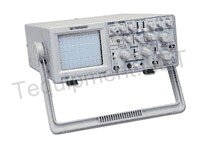
Figure 3.1: Front view of the B&K Precision 2190B Dual Trace Analog Oscilloscope. The image displays the main unit with its CRT screen on the left and various control knobs and input jacks on the right, including vertical and horizontal controls, trigger settings, and input channels.
Key Features:
- 100MHz Bandwidth: Capable of accurately displaying signals up to 100 MHz.
- Two Channels: Allows for simultaneous display and comparison of two independent signals.
- Vertical Sensitivity: Adjustable from 5mV/div to 1mV/div (with gain control) for capturing low-level signals.
- Rise Time: 3.5 ns
- Sweep Time: 0.05µs/div to 0.5s/div
- Trigger Modes: AUTO, NORM, TV-V, TV-H
- Trigger Source: CH1, CH2, ALT, LINE, EXT
- 6" CRT Display: Clear, variable-illumination cathode ray tube display with an 8x10 division internal grid.
4. Setup
- Placement: Place the oscilloscope on a stable, level surface with adequate ventilation. Ensure there is sufficient space around the unit for air circulation. Avoid direct sunlight, excessive dust, high humidity, or strong vibrations.
- Power Connection: Connect the provided power cord to the AC inlet on the rear panel of the oscilloscope and then to a grounded AC power outlet. Verify that the power supply voltage matches the rating specified on the oscilloscope's rear panel (100/120/220/240 V AC +/-10%, 50/60Hz).
- Probe Connection: Connect the oscilloscope probes to the BNC input connectors (CH1 and CH2) on the front panel. Ensure the probe's ground clip is securely connected to the circuit's ground point.
- Probe Compensation: Before taking measurements, compensate the probes to ensure accurate waveform display. Connect the probe to a channel input and its tip to the probe compensation output (usually a square wave signal). Adjust the compensation trimmer on the probe until a flat-top square wave is displayed on the screen.
5. Operating Instructions
5.1 Basic Operation
- Power On: Press the power switch to turn on the oscilloscope. Allow a few moments for the CRT to warm up and display a trace.
- Intensity and Focus: Adjust the INTENSITY and FOCUS knobs to achieve a clear, sharp trace.
- Positioning: Use the VERTICAL POSITION (for each channel) and HORIZONTAL POSITION knobs to move the trace to the desired position on the screen.
- Vertical Sensitivity (VOLTS/DIV): Select the appropriate VOLTS/DIV setting for the input signal. This determines the vertical scale of the waveform.
- Time Base (TIME/DIV): Select the appropriate TIME/DIV setting. This determines the horizontal scale (time per division) of the waveform.
5.2 Triggering
Triggering is crucial for obtaining a stable waveform display. The trigger circuit synchronizes the horizontal sweep with a specific point on the input signal.
- Trigger Source: Select the trigger source (CH1, CH2, ALT, LINE, EXT). For most applications, CH1 or CH2 is used.
- Trigger Mode: Choose between AUTO, NORM, or TV modes. AUTO provides a trace even without a trigger signal. NORM requires a trigger signal to display a trace. TV modes are for video signals.
- Trigger Level: Adjust the TRIGGER LEVEL knob to set the voltage point on the waveform where the sweep will begin.
- Slope: Select the trigger slope (positive or negative) to trigger on the rising or falling edge of the signal.
5.3 Dual Channel Operation (ALT Triggering)
To view both CH1 and CH2 signals simultaneously, ensure both channels are enabled and select the ALT trigger source. This mode rapidly alternates between displaying CH1 and CH2, creating the appearance of a simultaneous display.
5.4 Delayed Sweep
The delayed sweep function allows for detailed examination of a specific portion of a waveform. Engage the delayed sweep mode and use the delay time control to position the magnified section. The sweep speed can be magnified by 10 times for enhanced resolution.
6. Maintenance
Proper maintenance ensures the longevity and accuracy of your oscilloscope.
- Cleaning: Regularly clean the exterior of the oscilloscope with a soft, damp cloth. Do not use abrasive cleaners or solvents. Ensure the unit is powered off and unplugged before cleaning.
- Ventilation: Keep the ventilation openings clear of dust and obstructions to prevent overheating.
- Probe Care: Handle probes carefully. Avoid bending or kinking the cables. Store them properly to prevent damage to the tips and connectors.
- Fuse Replacement: If the oscilloscope does not power on, check the fuse located near the AC inlet. Replace it only with a fuse of the same type and rating as specified in the specifications or on the unit itself. Always unplug the power cord before replacing the fuse.
- Calibration: For continued accuracy, periodic calibration by qualified service personnel is recommended.
7. Troubleshooting
This section provides solutions to common issues you might encounter.
| Problem | Possible Cause | Solution |
|---|---|---|
| No trace on screen | Power off; Intensity too low; Focus out of adjustment; Vertical/Horizontal position off screen; No input signal; Trigger mode incorrect. | Check power; Adjust INTENSITY and FOCUS; Adjust POSITION knobs; Connect signal; Set trigger mode to AUTO or NORM with valid signal. |
| Unstable waveform | Incorrect trigger level; Incorrect trigger source; Signal too noisy; Probe compensation incorrect. | Adjust TRIGGER LEVEL; Select correct TRIGGER SOURCE; Use noise reduction techniques; Perform probe compensation. |
| Waveform too small/large | Incorrect VOLTS/DIV setting; Incorrect TIME/DIV setting. | Adjust VOLTS/DIV to match signal amplitude; Adjust TIME/DIV to match signal frequency. |
| Distorted waveform | Probe compensation incorrect; Probe damaged; Input signal issues. | Perform probe compensation; Check probe for damage; Verify input signal integrity. |
If the problem persists after attempting these solutions, please contact B&K Precision customer support.
8. Specifications
Detailed technical specifications for the B&K Precision 2190B Dual Trace Analog Oscilloscope:
- Bandwidth: 100 MHz
- Channels: Two (Dual Trace)
- Display: 6-inch CRT, 8 x 10 division grid (1cm per division)
- Vertical Sensitivity: 5mV/div to 5V/div (to 1mV/div with gain control)
- Rise Time: 3.5 ns
- Sweep Time: 0.05µs/div to 0.5s/div
- Trigger Modes: AUTO, NORM, TV-V, TV-H
- Trigger Source: CH1, CH2, ALT, LINE, EXT
- Power Requirements: 100/120/220/240 V AC +/-10%, 50/60Hz, approximately 55W
- Dimensions (H x W x D): 324 x 398 x 132 mm (12.76 x 15.68 x 5.2 inches)
- Weight: 8.5 kg (18.7 lb)
- Certifications: Underwriters Laboratories (UL) certified
9. Warranty and Support
B&K Precision products are manufactured to high quality standards and are backed by a limited warranty. For specific warranty terms and conditions, please refer to the warranty card included with your product or visit the official B&K Precision website.
For technical support, service, or inquiries regarding your 2190B oscilloscope, please contact B&K Precision customer service. Contact information can typically be found on the company's official website or in the product packaging.
B&K Precision Headquarters: Yorba Linda, CA, USA
Related documents2190B


Ask a question about this manual
Ask about setup, troubleshooting, compatibility, parts, safety, or missing instructions. Manuals+ will review the question and use this page’s manual context to help answer it.