1. Introduction
This user manual provides comprehensive instructions for the Supermicro X5DA8 motherboard. It covers essential information regarding installation, configuration, operation, and troubleshooting to ensure optimal performance and longevity of your system. Please read this manual thoroughly before installing or operating the motherboard.
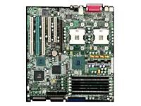
Figure 1: Supermicro X5DA8 Motherboard. This image displays the overall layout of the Supermicro X5DA8 motherboard, highlighting key components such as the CPU sockets, memory slots, and expansion slots.
2. Setup and Installation
2.1. Package Contents
Verify that all components are present in the motherboard package:
- Supermicro X5DA8 Motherboard
- I/O Shield
- SATA/IDE Cables (quantity may vary)
- Driver CD/DVD
- Quick Installation Guide
2.2. Hardware Installation
- Prepare the Chassis: Ensure your computer chassis is compatible with ATX form factor motherboards. Install the I/O shield into the chassis opening.
- Install the Motherboard: Carefully align the motherboard with the standoffs in the chassis. Secure it with screws, ensuring not to overtighten.
- Install CPUs: The X5DA8 supports dual Intel Xeon processors (Socket 604). Open the CPU socket retention mechanism, align the processor with the socket key, gently place it, and close the retention mechanism. Apply thermal paste and install the CPU coolers.
- Install Memory (RAM): This motherboard supports DDR RAM. Insert DDR memory modules into the available 6 memory slots. Ensure the modules are correctly oriented and firmly seated until the clips lock into place.
- Install Expansion Cards: Insert PCI graphics cards or other expansion cards into the appropriate PCI slots. Secure them with the chassis retention clips or screws.
- Connect Power Supply: Connect the 24-pin ATX main power connector and the 8-pin (or 4-pin) ATX 12V CPU power connector from your power supply to the motherboard.
- Connect Storage Devices: Connect SATA or IDE cables from your storage drives (hard drives, SSDs, optical drives) to the corresponding ports on the motherboard. Connect power cables from the power supply to these devices.
- Connect Front Panel Cables: Connect the front panel connectors (power button, reset button, HDD LED, power LED, USB ports, audio jacks) to the corresponding headers on the motherboard. Refer to the motherboard layout diagram for exact pin assignments.
3. Operating Instructions
3.1. Initial Boot-Up
After completing hardware installation, connect a monitor, keyboard, and mouse. Power on the system. The system will perform a Power-On Self-Test (POST). If successful, the BIOS screen will appear.
3.2. BIOS Configuration
To enter the BIOS setup utility, press the DEL key during POST. The BIOS allows you to configure system settings such as boot order, CPU settings, memory timings, and integrated peripherals. Save changes before exiting the BIOS.
3.3. Driver Installation
After installing your operating system (e.g., Windows 10), install the necessary drivers for the motherboard components. Use the provided driver CD/DVD or download the latest drivers from the Supermicro official website. Install drivers for chipset, LAN, audio, and any other integrated devices.
4. Maintenance
4.1. Cleaning
Regularly clean the interior of your computer chassis to prevent dust buildup, which can lead to overheating. Use compressed air to remove dust from fans, heatsinks, and motherboard components. Ensure the system is powered off and unplugged before cleaning.
4.2. BIOS Updates
Periodically check the Supermicro website for BIOS updates. BIOS updates can improve system stability, add support for new hardware, or fix known issues. Follow the instructions provided by Supermicro carefully when performing a BIOS update to avoid system damage.
4.3. Driver Updates
Keep your system drivers updated. Outdated drivers can cause performance issues or instability. Download the latest drivers from the Supermicro website or the respective component manufacturers.
5. Troubleshooting
5.1. No Power
- Check if the power supply is properly connected to the motherboard (24-pin ATX and 8-pin/4-pin CPU power).
- Ensure the power supply switch is in the 'ON' position.
- Verify that the front panel power button cable is correctly connected to the motherboard header.
5.2. No Display
- Ensure the monitor is connected and powered on.
- Reseat the graphics card in its PCI slot.
- Try a different graphics card or monitor if available.
- Check if memory modules are properly seated.
5.3. System Instability/Crashes
- Check CPU and system temperatures. Ensure cooling solutions are functioning correctly.
- Run memory diagnostic tools to check for faulty RAM modules.
- Ensure all drivers are up to date.
- Verify power supply stability and wattage.
6. Specifications
Key technical specifications for the Supermicro X5DA8 Motherboard:
| Feature | Specification |
|---|---|
| Brand | Supermicro |
| Model Number | MBD-X5DA8-O |
| CPU Socket | Socket 604 (Dual) |
| Compatible Processors | Intel Xeon |
| Chipset Type | Intel E7505 |
| RAM Memory Technology | DDR |
| Memory Slots Available | 6 |
| Maximum Memory Storage Capacity | 12 GB (as per product data, actual max may vary by module size) |
| Graphics Card Interface | PCI |
| System Bus Standard Supported | SATA 3 (Note: May also support IDE/SCSI depending on specific revision) |
| S/PDIF Connector Type | Optical |
| Compatible Devices | Server |
| Platform | Windows 10 (OS compatibility) |
| Item Weight | 8 Pounds |
| UPC / GTIN | 672042882076 |
7. Warranty and Support
Specific warranty terms and support information for the Supermicro X5DA8 motherboard are typically provided with the product packaging or available on the official Supermicro website. Please refer to the manufacturer's website or the documentation included with your purchase for the most accurate and up-to-date warranty details and technical support contacts.
For technical assistance, driver downloads, or BIOS updates, visit the official Supermicro support portal.


