ANALOG DEVICES MAX20363 Evaluation Board Kit

General Description
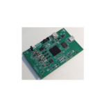
The MAX20363 evaluation kit (EV kit) is a fully assembled and tested circuit for evaluating MAX20363, non-inverting buck-boost converter for powering optical photoplethysmogram (PPG) systems. The device is configurable through an I2C interface that allows for programming various functions and reading device status. The EV kit GUI application sends commands to the MAXPICO2PMB# adapter board to configure the device. The EV kit comes standard with the MAX20363 EV kit version IC installed.
Features and Benefits
- Ultra-Fast Dynamic Voltage Scaling (DVS) with DirectAFE Control
- USB-Power Option
- Flexible Configuration
- On-Board Battery Simulation
- Sense Test Point for Output-Voltage Measurement
- Windows® 8/Windows 10-Compatible Graphical UserInterface (GUI) Software
- Fully Assembled and Tested
EV KIT Contents
- MAX20363_EVKIT_A System
- MAXPICO2PMB# Board
- Two USB A to USB Micro-B Cables
MAX20363 EV Kit Files
FILE DESCRIPTION
- MAX20363GUI_SetupX.X.X.exe
- PC GUI Program
Quick Start
Required Equipment
- MAX20363 EV kit
- Windows PC with USB ports
- One USB A-to-USB Micro-B cable and PICO2PMBadapter board with the latest firmware
- One USB A-to-USB Micro-B cable or power supply (for battery voltage)
- One voltmeter
Note: In the following sections, software-related items are identified in bold. Text in bold refers to items directly from the EV kit software. Text in bold and underlined refers to items from the Windows operating system.
Procedure
The EV kit is fully assembled and tested. Follow the steps to install the EV kit software, make required hardware connections, and start operation of the kit.
- Visit www.analog.com/en/design-center/evaluation-hardware-and-software/evaluation-boards-kits under the “Design & Development” tab to download the latest version of the MAX20363 EV kit software. Save the software to a temporary folder and unpack the zip file.
- Install the EV kit software on the computer by running the MAX20363GUI_SetupX.X.X.exe program inside the temporary folder. This copies the program files and creates an icon in the Windows Start menu. The software requires the .NET Framework 4.5 or later. If connected to the internet, Windows automatically updates the .NET Framework as needed.
- The EV kit software launches automatically after installation, and it can be launched by clicking its icon in the Windows Start menu.
- Verify that all jumpers are in their default positions, as shown in Table 1.
- Connect the type-A end of a cable to the PC and the micro-USB end of a cable to the MAXPICO2PMB#board, and connect the MAXPICO2PMB# to J4 located on the top left of the EV kit board. Verify that LED DS10is illuminated.
- Connect a USB to the micro-B cable from the computer to J1 on the lower left corner of the EV kit board to use VBUS to power MAX20363. Verify that LED DS1 is illuminated. Use a voltmeter to check TP15 BATvoltage and it should be about 5V.
Information furnished by Analog Devices is believed to be accurate and reliable. However, no responsibility is assumed by Analog Devices for its use, nor for any infringements of patents or other rights of third parties that may result from its use. Specifications subject to change without notice. No license is granted by implication or otherwise under any patent or patent rights of Analog Devices. Trademarks and registered trademarks are the property of their respective owners.
©2024 Analog Devices, Inc. All rights reserved. Trademarks and registered trademarks are the property of their respective owners. www.analog.com
Documents / Resources
 |
ANALOG DEVICES MAX20363 Evaluation Board Kit [pdf] Instructions MAX20363 Evaluation Board Kit, MAX20363, Evaluation Board Kit, Board Kit |