ANALOG DEVICES LTP8800-1A 54V Input High Current DC Power Module with PMBus Interface

Product Information
| Product Name | DC3190A-A |
|---|---|
| Description | LTP8800-1A 54V Input, High Current DC/DC Power |
Product Usage Instructions
- Connect the input power supply to VIN (45V to 65V) and GND.
- Connect the auxiliary power supply to BIAS (7V) and GND.
- Connect the auxiliary power supply to 3V3 (3.3V) and GND.
- Connect the load from VOUT to GND.
- Connect the DMMs to the input and outputs.
- Adjust the load current within the operating range of 0A to 150A.
- Observe the output voltage regulation, output voltage ripples, load transient response, and other parameters.
- Connect the dongle and control the output voltages from the GUI. Refer to LTpowerPlay GUI for the LTP8800-1A Quick Start Guide for details.
Measurement Equipment Setup
Refer to Figure 1 for the proper measurement equipment setup.

Connect PC to DC3190A-A
Use a PC to reconfigure the power management features of the LTP8800-1A. LTpowerPlay software can be downloaded from: LTpowerPlay. To access technical support documents for Analog Devices Digital Power Products, visit the LTpowerPlay Help menu. Online help is also available through LTpowerPlay.
Typical Performance Characteristics
Measured LTP8800-1A efficiency at VIN = 54V, fSW = 1MHz, Forced Air Cooled with 500LFM:

DESCRIPTION
Demonstration circuit 3190A-A is a high current, high density, high-efficiency open-frame μModule® regulator with 45V to 65V input range. The demo board has an LTP™8800-1A μModule regulator which provides a microprocessor 0.75V voltage from 54V power distribution architecture with digital power system management. The maximum output current for the demo board is 150A. Please see the LTP8800-1A data sheet for more detailed information. DC3190A-A powers up to default settings and produces power based on configuration resistors without the need for any serial bus communication. This allows easy evaluation of the DC/DC converter. To fully explore the extensive power system management features of the part, download the GUI software LTpowerPlay® onto your PC and use ADI’s I2C/SMBus/PMBus dongle DC1613A to connect to the board. LTpowerPlay allows the user to reconfigure the part on-the-fly and store the configuration in EEPROM, view telemetry of voltage, current, temperature and fault status.
GUI Download
The software can be downloaded from:
LTpowerPlay For more details and instructions of LTpowerPlay, please refer to LTpowerPlay GUI for LTP8800-1A Quick Start Guide.
Design files for this circuit board are available.
All registered trademarks and trademarks are the property of their respective owners.
BOARD PHOTO
Part marking is either ink mark or laser mark
PERFORMANCE SUMMARY
Specifications are at TA = 25°C, Air cooling 400LFM
QUICK START PROCEDURE
Demonstration circuit 3190A-A is easy to set up to evalu-ate the performance of the LTP8800-1A.
Refer to Figure 1 for the proper measurement equipment setup and follow the procedure below:
- With power off, connect the input power supply to VIN (45V to 65V) and GND.
- With power off, connect the auxiliary power supply to BIAS (7V) and GND.
- With power off, connect the auxiliary power supply to 3V3 (3.3V) and GND.
- With power off, connect the load from VOUT to GND.
- Connect the DMMs to the input and outputs.
- Turn on the auxiliary power supply and the input power supply and check for the proper output voltage. VOUT should be 0.75V ±0.5%.
- Once the input and output voltages are properly estab-lished, adjust the load current within the operating range of 0A to 150A. Observe the output voltage regulation, output voltage ripples, load transient response and other parameters.
- Connect the dongle and control the output voltages from the GUI. See LTpowerPlay GUI for the LTP8800-1A Quick Start Guide for details.
Note: When measuring the output or input voltage ripple, do not use the long ground lead on the oscil-loscope probe. See Figure 2 for the proper scope probe technique. Short, stiff leads need to be soldered to the (+) and (–) terminals of an output capacitor. The probe’s ground ring needs to touch the (–) lead and the probe tip needs to touch the (+) lead.
Figure 1. Proper Measurement Equipment Setup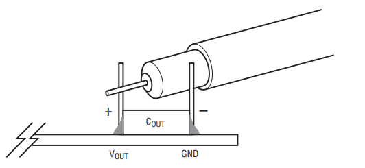
Figure 2. Measuring Output Voltage Ripple
CONNECT PC TO DC3190A-A
Use a PC to reconfigure the power management features of the LTP8800-1A such as: nominal VOUT, margin set points, OV/UV limits, temperature fault limits, sequenc-ing parameters, the fault log, fault responses, GPIOs and other functionalities. LTpowerPlay utilizes the DC1613A USB-to-SMBus controller to communicate with one of demo system, or a customer board. The software also provides an automatic update feature to keep the software current with the latest set of device drivers and docu-mentation. The LTpowerPlay software can be downloaded from: LTpowerPlay. To access technical support documents for Analog Devices Digital Power Products, visit the LTpowerPlay Help menu. Online help also available through the LTpowerPlay.
Figure 3. LTpowerPlay Main Interface
TYPICAL PERFORMANCE CHARACTERISTICS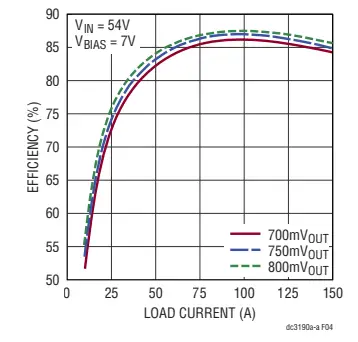
Figure 4. Measured LTP8800-1A Efficiency at VIN = 54V, fSW = 1MHz, Forced Air Cooled with 500LFM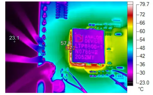
Figure 5. LTP8800-1A Thermal Performance at VIN = 54V, ILOAD = 150A, TA = 25°C, 500LFM Forced Airflow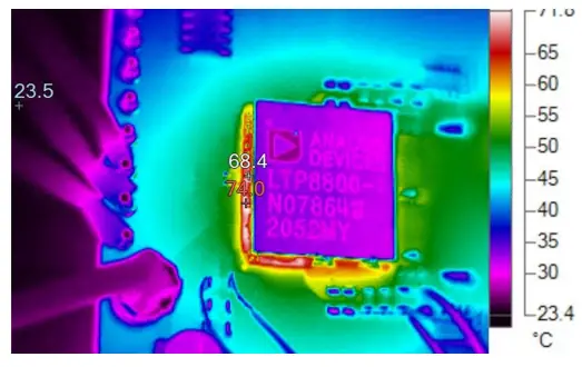
Figure 6. LTP8800-1A Thermal Performance at VIN = 54V, ILOAD = 150A, TA = 25°C, 900LFM Forced Airflow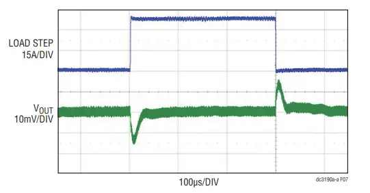
Figure 7. LTP8800-1A Load Transient Responses with Load Steps 0A to 37.5A to 0A at di/dt = 37.5A/µs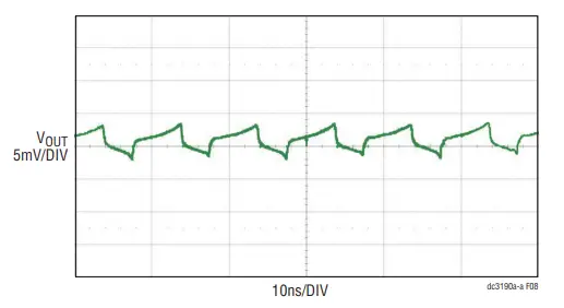
Figure 8. LTP8800-1A DC3190A-A Output Voltage Ripple Measured Through J3 (54V Input, IOUT = 150A, 20MHz BW Limit)
PARTS LIST

SCHEMATIC DIAGRAM
Information furnished by Analog Devices is believed to be accurate and reliable. However, no responsibility is assumed by Analog Devices for its use, nor for any infringements of patents or other rights of third parties that may result from its use. Specifications subject to change without notice. No license is granted by implication or otherwise under any patent or patent rights of Analog Devices.
REVISION HISTORY
ESD Caution
ESD (electrostatic discharge) sensitive device. Charged devices and circuit boards can discharge without detection. Although this product features patented or proprietary protection circuitry, damage may occur on devices subjected to high energy ESD. Therefore, proper ESD precautions should be taken to avoid performance degradation or loss of functionality.
ANALOG DEVICES, INC. 2023
Documents / Resources
 |
ANALOG DEVICES LTP8800-1A 54V Input High Current DC Power Module with PMBus Interface [pdf] Instruction Manual DC3190A-A, LTP8800-1A 54V Input High Current DC Power Module with PMBus Interface, LTP8800-1A High Current DC Power Module with PMBus Interface, 54V Input High Current DC Power Module with PMBus Interface, High Current DC Power Module with PMBus Interface, High Current DC Power Module, DC Power Module, DC Module, Module |