![]() User Guide | EVAL-ADMT4000
User Guide | EVAL-ADMT4000
UG-2069
Evaluating the ADMT4000
Zero Power Multiturn Sensor
FEATURES
► Full featured evaluation board for the ADMT4000
► Magnetic reset
► PC control with the System Demonstration Platform, SDP (EVALSDP-CS1Z)
► PC software for configuration and data measurement
EVALUATION KIT CONTENTS
► EVAL-ADMT4000SD1Z evaluation board
► Magnet stimulus
► Dipole magnet
► Hand movable mounting
HARDWARE REQUIRED
► The EVAL-SDP-CS1Z or EVAL-SDP-CB1Z controller board
► USB cable supplied with the EVAL-SDP-CS1Z
SOFTWARE REQUIRED
► EVAL-ADMT4000SD1Z software
GENERAL DESCRIPTION
The ADMT4000 is a magnetic turn, counter sensor capable of recording turns of an external magnetic field with zero power. The absolute position, including the number of turns, is reported via a serial peripheral interface (SPI). The EVAL-ADMT4000SD1Z evaluation board allows for the evaluation of the ADMT4000 zero power, multiturn sensor by providing a flexible hardware platform with accompanying graphical user interface (GUI). The
EVAL-ADMT4000SD1Z features the ADMT4000 in an end of shaft magnet configuration, Figure 1. The evaluation kit is composed of an EVAL-ADMT4000SD1Z and a magnetic stimulus on a printed circuit board (PCB) mount. To operate with the provided GUI, the EVAL-SDP-CS1Z (SDP-S) or EVAL-SDP-CB1Z (SDP-B) is required, interchangeably referred to as the SDP controller board within this user guide.
 Figure 1. ADMT4000 End of Shaft Magnetic Evaluation System Comprises the EVAL-ADMT4000SD1Z,
the SDP Interface, and the EVAL-ADMT4000SD1Z GUI
PLEASE SEE THE LAST PAGE FOR AN IMPORTANT WARNING AND LEGAL TERMS AND CONDITIONS.
GETTING STARTED
QUICK START STEPS
The EVAL-ADMT4000SD1Z evaluation board, Figure 2, connects to either the EVAL-SDP-CS1Z (SDP-S) or EVAL-SDP-CB1Z (SDP-B). In this user guide, SDP refers to either of these controller boards. The SDP is the communication link between the PC and the
EVAL-ADMT4000SD1Z, and the SDP provides the SPI required to control the ADMT4000 and send captured data directly to the host PC.
The EVAL-ADMT4000SD1Z evaluation software and drivers must be installed before connecting the evaluation board and SDP controller board to the USB port of the PC to ensure that the evaluation system is correctly recognized when it connects.
To begin using the EVAL-ADMT4000SD1Z, take the following steps:
- Install the EVAL-ADMT4000SD1Z software. See the Installing the EVAL-ADMT4000SD1Z Software section for additional information.
- Connect the SDP to the EVAL-ADMT4000SD1Z.
- Slide the EVAL-ADMT4000SD1Z into the magnet mounting bracket. To correctly align the magnet with the ADMT4000 sensor, ensure that the EVAL-ADMT4000SD1Z is fully inserted into the magnet PCB mount.
- Connect the SDP to the PC using the supplied USB cable (USB Type A to Mini-B).
- Launch the EVAL-ADMT4000SD1Z software. Click the Windows® key to open the Windows Start Menu and Programs list. Navigate to Analog Devices and click EVALADMT4000SDZ.
 Figure 2. Hardware Configuration Showing the Demonstration Magnet
Assembly and the EVAL-ADMT4000SD1Z
EVALUATION BOARD
The EVAL-ADMT4000SD1Z was designed to enable the user to get started quickly with the ADMT4000 using the supplied evaluation software and SDP interface.
By making use of the headers on the EVAL-ADMT4000SD1Z, Table 1, the user can connect an alternative microprocessor to develop custom software. The PCB section, where the ADMT4000 is mounted, was designed to allow the user to mount the board in a space limited environment by removing the break away section from the interface section. Headers are provided on the break away section to enable operation of the ADMT4000 with a microprocessor.
ADMT4000 MAGNETIC SENSING
The position of the ADMT4000 angle sensor with respect to the center of the IC package is detailed in the ADMT4000 data sheet. The magnet assembly correctly aligns the supplied magnet with the ADMT4000 sensor when the PCB is fully inserted into the magnet assembly. A diametrical oriented disk magnet (diameter 10 mm and height 5 mm) is supplied with the EVAL-ADMT4000SD1Z evaluation kit. The magnet is manufactured from samarium (Sm)2 -colbalt (Co)17 with a remanence (Br) of 950 mT to 1020 mT.
ADMT4000 OUTPUTS
The ADMT4000 outputs angular position data, device status, and diagnostics over the SPI.
POWER SUPPLIES
The EVAL-ADMT4000SD1Z uses the 3.3 V supply from the SDP interface to power all the components on the board except for the LT3461, which is powered from the 5 V USB. The LT3461 is a step up DC/DC converter used for the magnetic reset circuit. It is possible to use external supplies by connecting through various headers, as shown in Figure 24 and Figure 25 and described in the Table 1.
ADMT4000 BOARD BREAK AWAY SECTION
The EVAL-ADMT4000SD1Z includes a break away section. The SDP interface circuitry can be removed by snapping the narrow bridges of the evaluation board located in the middle of the EVALADMT4000SD1Z. Removing the SDP interface circuitry allows the user to make use of a smaller standalone evaluation board. The ADMT4000 can be connected to an external system that supplies the power and controls the digital interfaces.
EVALUATION KIT CONNECTORS
The PCB headers for connecting external systems to the EVAL-ADMT4000SD1Z are listed in Table 1.
Table 1. Summary of the EVAL-ADMT4000SD1Z Evaluation Kit Headers
| Identifier | Description |
| P1 | Socket for the SDP interface board |
| P2 | Header for the RSTB, CNV, BUSY, and GPIO4 signals |
| P3 | Header for the SPI signals |
| P4 | Header that allows access to the I²C, SPI, status, and control generalpurpose input and output (GPIO) from the breakaway section |
| P5 | Header for the magnetic reset coil |
| P6 | Header for a differential coil to measure the current in magnetic reset coil |
| P7 | Header for access to key signals on the breakaway section |
Table 2 through Table 8 details the connections to the headers available on the EVAL-ADMT4000SD1Z.
Table 2. P1 Socket for the SDP Interface Controller Board
| Pin Number | Mnemonic | Description |
| 3, 4, 6, 11, 17, 23, 28, 36, 40, 46, 52, 58, 63, 69, 75, 81, 86, 93, 98, 104, 109, 115, 117, 118 |
GND | System ground |
| 5 | USB_V | 5 V supply from the USB port of the connected PC |
| 38 | SPI CSB | SPI chip select for the ADMT4000, SDP Chip Select Port C |
| 43 | GPIO3_ACALC | GPIO or angle calculation status |
| 44 | COIL_RS | Magnetic reset-coil reset enable |
| 45 | GPIO0_BUSY | GPIO or busy status output |
| 46 | V_EN | VDD enable for the ADMT4000 |
| 56 | EEPROM_A0 | Address A0 of the board identifier electrically erasable programmable readonly memory (EEPROM) |
| 74 | RSTB | ADMT4000 reset function |
| 76 | GPIO1_CNV | GPIO or convert start |
| 77 | BOOST_EN | Magnetic reset-coil boost circuit enable |
| 78 | GPIO4 | GPIO or fault status |
| 79 | I2C SCL_0 | I²C clock |
| 80 | I2C SDA_0 | I²C data |
| 82 | SPI SCLK | SPI clock |
| 83 | SPI SDO | SPI subordinate data out |
| 84 | SPI SDI | SPI subordinate data in |
| 85 | SPI_SEL_A_N | SPI chip select for the GPIO expander, SDP Chip Select A |
| 116 | 3V3 | Main supply for the ADMT4000 and supporting devices |
Table 3. P2 Header for the RSTB, CNV, BUSY, and GPIO4 Signal
| Pin Number | Mnemonic | Description |
| 1 | RSTB | ADMT4000 reset function |
| 2 | GPIO1_CNV | GPIO1 and convert start |
| 3 | GPIO0_BUSY | GPIO0 and busy status output |
| 4 | GPIO4 | GPIO4 |
| 5 | GND | System ground |
Table 4. P3 Header for SPI
| Pin Number | Mnemonic | Description |
| 1 | I2C SCLK | I2C clock |
| 2 | SPI SDO | SPI data out |
| 3 | SPI SDI | SPI data in |
| 4 | SPI CSB | SPI chip select for the ADMT4000, SDP Chip Select Port C |
Table 5. P4 External Interface Header
| Pin Number | Mnemonic | Description |
| 1 | 3V3 | Main supply for the ADMT4000 and supporting devices |
| 2 | GND | System ground |
| 3 | 5V | Supply for the magnetic reset coil |
| 4 | SPI SCLK | SPI clock |
| 5 | SPI SDO | SPI data out |
| 6 | SPI SDI | SPI data in |
| 7 | SPI CSB | SPI chip select |
| 8 | RSTB | ADMT4000 reset function |
| 9 | GPIO1_CNV | GPIO1 or convert start |
| 10 | GPIO0_BUSY | GPIO0 or busy status output |
| 11 | GPIO4 | GPIO4 |
| 12 | GPIO5_BOOTLOA D | GPIO5 or bootload status |
| 13 | GPIO3_ACALC | GPIO3 or angle calculation status |
| 14 | I2C SDA_0 | I2C data |
| 15 | I2C SCL_0 | I2C clock |
| 16 | V_EN | VDD enable for the ADMT4000 |
| 17 | BOOST_EN | Magnetic reset-coil boost circuit enable |
| 18 | COIL_RS | Magnetic reset-coil reset enable |
Table 6. P5 Header for the Magnetic Reset Coil
| Pin Number | Mnemonic | Description |
| 1 | COIL+ | Positive terminal of the magnetic reset coil. |
| 2 | COIL− | Negative terminal of the magnetic reset coil. |
Table 7. P6 Header for a Differential Coil to Measure the Current in Magnetic Reset Coil
| Pin Number | Mnemonic | Description |
| 1 | COIL+ | High-side sense resistor voltage |
| 2 | COIL++ | Low-side sense resistor voltage |
Table 8. P7 Header to Allow Access to the I²C, SPI, Status, and Control GPIO from the Breakaway Section
| Pin Number | Mnemonic | Description |
| 1 | VDD | Direct power supply to the ADMT4000 |
| 2 | 5V | 5 V supply for alternative VDRIVE level |
| 3 | GPIO2 | GPIO |
| 4 | I2C SCLK_I | SPI clock |
| 5 | SPI SDO_I | SPI data out |
| 6 | SPI SDI_I | SPI data in |
| 7 | SPI CSB_I | SPI chip select for the ADMT4000 |
| 8 | RSTB_I | ADMT4000 reset function |
| 9 | CNV_I | Convert start |
| 10 | GPIO0_BUSY | GPIO or busy status output |
| 11 | GPIO4 | GPIO |
| 12 | GPIO5_BOOTLOAD | GPIO or bootload status |
| 13 | GPIO3_ACALC | GPIO or angle calculation status |
| 14 | GND | System ground |
| 15 | VRDIVE | ADMT4000 GPIO supply |
SOFTWARE INSTALLATION
The Installing the EVAL-ADMT4000SD1Z Software and Installing the System Demonstration Platform Board Drivers sections outline the software installation process assuming that the SDP drivers have not been previously installed.
INSTALLING THE EVAL-ADMT4000SD1Z SOFTWARE
To install the EVAL-ADMT4000SD1Z software, take the following steps:
- Run the EVAL-ADMT4000SDZ.exe file supplied on the ADMT4000 product page to install the EVAL-ADMT4000SDZ software. If a dialog box appears to ask for permission to allow the program to make changes to the PC, click Yes.
- Select the location to install the software to and then click Next (see Figure 3).
 Figure 3. ADMT4000 Installation Path
 - A summary of the installation then displays. Click Next to continue (see Figure 4).
 Figure 4. ADMT4000 Installation Summary
 - When the installation completes, click Finish (see Figure 5).
 Figure 5. ADMT4000 Installation Complete
INSTALLING THE SYSTEM DEMONSTRATION PLATFORM BOARD DRIVERS
After the installation of the EVAL-ADMT4000SD1Z software is complete, a welcome window displays (see Figure 6) for the installation of the SDP drivers.
Take the following steps to install the SDP drivers:
- With the SDP board disconnected from the USB port of the PC, make sure that all other applications are closed, and then click Next.
 Figure 6. SDP Platform Installation
 - A license agreement then appears. Read the agreement, select I accept the License Agreement, and click Next and then I Agree (see Figure 7).
 Figure 7. SDP Platform License
 - The Choose Components window then appears with default components preselected. Click Next (see Figure 8).
 Figure 8. SDP Component Selection
 - Select the location to install the drivers, and then click Install (see Figure 9).
 Figure 9. SDP Platform Installation Folder
 - To complete the installation of the driver, click Close, which closes the installation wizard (see Figure 10).
 Figure 10. SDP Installation Complete
 - The driver installation then installs the Windows drivers. If Windows Security requests permission to install, click Install (see Figure 11).
 Figure 11. SDP Drivers Install
EEPROM CONFIGURATION
The EEPROM on the EVAL-ADMT4000SD1Z daughter board stores the daughter board type and is factory set. If the EEPROM is not programmed, or an invalid daughter board is connected, a dialog box as shown in Figure 12 appears.
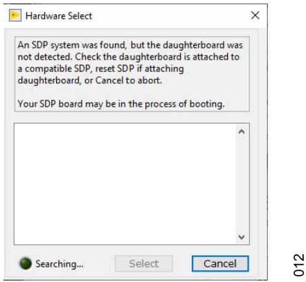 Figure 12. Pop-Up Window Indicating That Either an Unexpected Daughter Board Is Attached to the SDP or That the EVAL-ADMT4000SD1ZEEPROM Was Incorrectly Programmed
To configure the EEPRPOM, launch the SDP EEPROM Programmer (.NET) utility, which is available from Analog Devices, Inc., Sales.
The appropriate .dat file is also available upon request to configure the Load File tab, as shown in Figure 13, which uses Address 54.
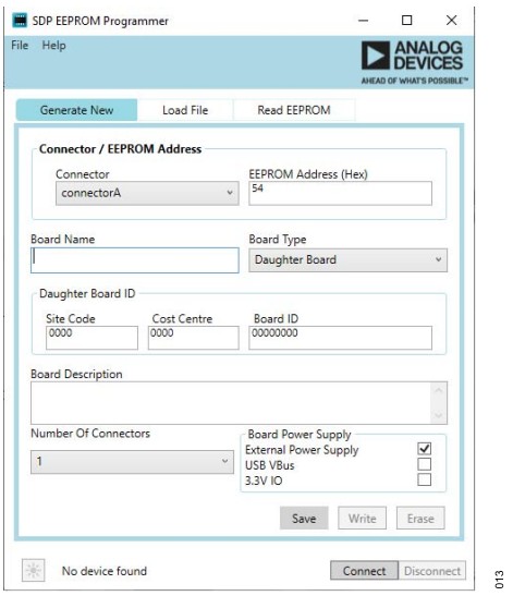 Figure 13. SDP EEPROM Configuration Utility
EVAL-ADMT4000SD1Z SOFTWARE OPERATION
The Overview of the ADMT4000 Evaluation GUI and the Starting the EVAL-ADMT4000SD1Z Software sections describes how to operate the GUI provided in the EVAL-ADMT4000SD1Z software.
STARTING THE EVAL-ADMT4000SD1Z SOFTWARE
After completing the steps in the Software Installation section, launch the EVAL-ADMT4000SD1Z software as follows:
► Connect the SDP with the EVAL-ADMT4000SD1Z to the PC using the provided USB cable.
► Click the Windows icon to open the Windows Start menu and Programs list. Select Analog Devices/EVAL-ADMT4000SD1Z.
► If the ADMT4000 Evaluation GUI is successfully installed and the EVAL-ADMT4000SD1Z is detected, the EVALADMT4000SD1Z evaluation software automatically opens (see Figure 14). The evaluation board name displays on the front panel of the GUI (see Label 1 in Figure 14).
 Figure 14. ADMT4000 Evaluation GUI Showing the Connected
EVALADMT4000SD1Z Evaluation Kit
► If the EVAL-ADMT4000SD1Z evaluation system is not connected to the USB port via the SDP, the evaluation board name does not display on the front panel. After a few seconds, the Hardware Select window appears (see Figure 15). Connect the EVAL-ADMT4000SD1Z evaluation system to the USB port of the PC and wait a few seconds. The Hardware Select window then shows the SDP evaluation kits connected to the PC. Select the EVAL-ADMT4000SD1Z and click Select (see Figure 16).
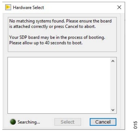 Figure 15. Hardware Select Window That Appears When the GUI Starts
Without the EVAL-ADMT4000SD1Z Connected to the PC
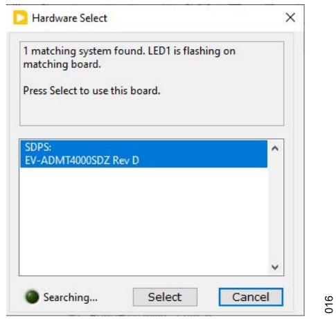 Figure 16. Hardware Select Window That Appears When the
EVALADMT4000SD1Z Connects to the PC
► On startup, the ADMT4000 Evaluation GUI automatically begins to acquire and display data from the ADMT4000. The initial sequence settings are defined in the supplied configuration file C:\Program Files\Analog Devices\EVAL-ADMT4000SDZ 0.0.0\dataADMT4000 Config.csv. To start the GUI in a user-defined configuration, the user must modify the configuration file.
OVERVIEW OF THE ADMT4000 EVALUATION GUI
The ADMT4000 Evaluation GUI provides a series of tabs to allow the user to evaluate the features of the ADMT4000. The GUI tabs are shown and labeled in Figure 17. Table 9 outlines the key function accessed in the tabs.
 Figure 17. GUI Tab Menu
Table 9. Descriptions of the ADMT4000 Evaluation GUI Tabs with Labels
| Label Number | Tab Name | Description |
| 1 | Data Acquisition | The Data Acquisition tab is the primary user tab for monitoring the output from the ADMT4000 and for configuring the acquisition sequence. |
| 2 | Utility | The Utility tab displays the details of the FAULT register status and allows the upload of the user configuration and logging of SPI commands. |
| 3 | Calibration | The Calibration tab is where the user configures system-level calibration. |
Data Acquisition Tab
The Data Acquisition tab (see Figure 18) displays sensor measurements and gives access to the sensor diagnostics.
 Figure 18. Data Acquisition Tab
Table 10 gives a description of the labels in the Data Acquisition tab, Figure 18.
Table 10. Descriptions for the Data Acquisition Tab Labels
| Label Number | Label Name | Description |
| 1 | Sequence control | Controls for selecting the measurement sequence settings. |
| 2 | Start or Pause | Begins the configured sequence or pauses the current sequence. |
| 3 | Reset | Performs a magnetic reset with the coil integrated into the evaluation kit. |
| 4 | Sine and Cosine | Plots the sine output vs. the cosine output. |
| 5 | Data Log | Enables data logging of the samples. |
| 6 | TMP (°C) | Is the internal temperature sensor display |
| 7 | Latest measurement | Displays the latest angle, turn count, and SPI frame counter. The device identification is updated on startup only. |
| 8 | Captured Data | Plot area for the sampled data. Displays the turn count, angle, and available diagnostic values. |
| 9 | Display Length | Controls the number of data points displayed on the Captured Data plot. |
| 10 | Power | . Controls the application of power to the ADMT4000. |
| 11 | Stop | Quits the GUI |
| 12 | Device Status | Indicators that turn red if a fault flag is detected on a SPI frame (Not active for Industrial applications), a cyclic redundancy check (CRC) error is detected on a SPI frame, or a fault flag is set in the FAULT register. |
| 13 | Help (?) icon | An example of the help icons that provide additional information for the user. |
Sequence Control
The Sequence control area in the Data Acquisition tab enables the user to configure the ADMT4000 acquisition mode as follows:
► Within the Conversion Type dropdown menu, select either CONTINUOUS or ONE SHOT acquisitions.
► Within CNV Source dropdown menu, select either the softwaregenerated convert start or an externally generated CNV. The external CNV signal is generated by the SDP controller board.
► Within the Convert Synchronization dropdown menu, the use of an external source to synchronize angle measurements is available.
► Within the Angle Filter dropdown menu, enable or disable the infinite impulse response (IIR) angle filter.
► Within the 8th Harmonic dropdown menu, select between the factory set 8th harmonic coefficient or a user-defined value coefficient in the ADMT4000 Config.csv configuration file.
EVAL-ADMT4000SD1Z SOFTWARE OPERATION
Start
The Start button is used to initiate or pause a measurement se-quence. Note that the label on the Start button changes to Pause once an acquisition is in progress.
Reset
The RESET button initiates a magnetic reset of the turn-count sensor using the coil on the EVAL-ADMT4000SD1Z as follows:
► Start a conversion sequence.
► Click Reset.
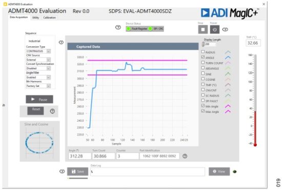 Figure 19. Captured Data Display Showing the Acquired Angle (Blue) and the Target Maximum and Minimum Angle (Magenta) for the Magnetic Reset
► The Captured Data display then shows the ANGLE measurement and a Min Angle and Max Angle target (see Figure 19).
► Rotate the magnet until the ANGLE measurement is within the limits shown in Figure 19.
► Click Reset, Label 3 in Figure 18.
► When operating in the ONE SHOT conversion type, the Turn Count indicator displays a value close to 46. Note that the exact value depends on the exact angle of the magnet.
► When operating in the CONTINUOUS conversion type, the user must restart the conversion sequence to observe the reset turn count.
► Turn the magnet counterclockwise to observe the turn counts decrementing.
Sine and Cosine
This area displays the magnitude of the sine vs. cosine measure-ments.
Data Log
The Data Log area, Figure 20, allows the user to save the captured data to an NI TDMS log file as follows:
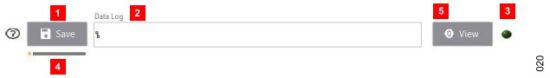 Figure 20. Captured Data Log Area of the Data Acquisition Tab
► The Save function can be started before or during an acquisition sequence. Note that it does not save any data gathered by the GUI before the save function is activated.
► Click Save (Label 1 in Figure 20) and a window then appears. The user can modify the file name and save location within this window. Ensure that the file extension is .tdms.
► The file path for the logged data is displayed in the Data Log indicator (Label 2 in Figure 20), and the save active indicator (Label 3 in Figure 20) changes from dark green to light green.
► To stop the save function, click Save (Label 1 in Figure 20).
► The save active indicator (Label 3 in Figure 20) then changes from light green to dark green.
► To optimize the TDMS file, the GUI automatically defragments the file, and the progress of this defragmentation process is shown in the progress bar (see Label 4 in Figure 20).
► To open the file location, click VIEW (Label 5 in Figure 20).
The TDMS file can be imported to Excel by using a free NI TDM Excel Add-In for Microsoft Excel, which can be downloaded from the NI website. The log file stores the device configuration, measured data, and fault status for each acquisition.
Temperature Sensor
The junction temperature is reported as both a thermometer display and digital display.
Latest Measurement
The last Angle and Turn Count data is displayed in the Latest Measurement area of the Data Acquisition tab (Label 7 in Figure 18).
► The Angle indicator shows the ANGLE data in degrees.
► The Turn Count indicator shows the number of turns.
► The Counter indicator shows the SPI frame count.
► The Part Identification indicator shows the unique identifier of the device connected to the EVAL-ADMT4000SD1Z.
Captured Data
The Captured Data section (Label 8 in Figure 18) displays a history of the data acquisitions. The tick boxes on the plot legend can control the visibility of data items on the plot. Note that the logged data contains all the data shown in the plot legend irrespective of
the state of the check box next to the plot name.
Display Length
The Display Length control (Label 9 in Figure 18) is used to control the number of data points displayed on the Captured Data plot.
Power
Click Power (Label 10 in Figure 18) to control the power mode of the ADMT4000.
 Figure 21. Power Button
The GUI attempts to read from the ADMT4000 irrespective of its power state.
Stop
Click Stop (Label 11 in Figure 18) to stop and quit the GUI.
Device Status
The following three fault status indicators (Label 13 in Figure 18) within the Device Status area display the fault statues of the latest SPI frame:
► Fault Register indicates that a flag is set in the FAULT register.
► SPI CRC indicates if a SPI frame CRC fault is detected.
► SPI Flag is the fault flag, which is contained within the ADMT4000 SPI frame that indicates that a flag is set in the FAULT register of the ADMT4000.
Help
There are several HELP buttons distributed around the ADMT4000 Evaluation GUI, for example, see Label 13 in Figure 18. Help features like this one are designed to aid the user with selected features.
Utility Tab
The Utility tab (see Figure 22) gives access to the FAULT register and allows control of the GPIOs of the ADMT4000, in addition to other resources, which are outlined in the following sections.
 Figure 22. Utility Tab
Table 11 gives a description of the labels in the Utility tab (see Figure 22).
Table 11. Descriptions for the Utility Tab Labels
| Label Number | Label Name | Description |
| 1 | Command Log | Logs the SPI commands generated by the GUI |
| 2 | DIGIO Functions | Enables control of the GPIO port functions |
| 3 | GPIO Monitor | GPIO current status |
| 4 | FAULT Register | FAULT register status |
| 5 | SPI Clock Frequency (Hz) | SPI clock frequency control |
| 6 | User configuration | User configuration control |
Command Log
The Command Log (Label 1 in Figure 22) can capture the SPI commands issued by the GUI for controlling the ADMT4000. To enable this feature, select the Record Enable check box. Click SAVE to save the log, and click the Recycle Bin icon to clear the log.
DIGIO Function
The GPIO ports on the ADMT4000 can be configured with the DIG-IO Function control (Label 2 in Figure 22). When the ADMT4000 Evaluation GUI starts, the GPIO ports step up according to the ADMT4000 Config.csv configuration file. Note that it is possible to select the functions in the Port dropdown menu to change operation of these ports.
GPIO Monitor
The GPIO Monitor (Label 3 in Figure 22) displays the current logic level of the GPIO ports. Light green indicates a high state on the port, and dark green indicates a low state.
FAULT Register
The FAULT Register (Label 4 in Figure 22) displays the latest status of the FAULT register of the ADMT4000, light red indicates that the FAULT flag is set, and dark red indicates that a fault is detected. In Figure 22, the FAULT register shows that no faults are detected.
SPI Clock Frequency (Hz)
To modify the SDP SPI clock, update the SPI Clock Frequency (Hz) box (Label 5 in Figure 22).
User Configuration
To upload a configuration file at any time, go to the User Configuration area of the Utility tab (Label 6 in Figure 22) and do the following:
► Select the required user configuration file.
► Click Upload.
► Once the configuration file uploads, the ADMT4000 is reconfigured. Note that the Read Reg Report window displays the state of the user registers following a reconfiguration.
Configuration File
The configuration file for the EVAL-ADMT4000SD1Z contains the ADMT4000 Evaluation GUI start-up settings, which set the ADMT4000 to a user-defined state at the launch of the application. The register names cannot be altered; however, the user is free to modify the register settings that follow the register name. The file must be saved in a comma separated *.csv format.
The contents of the supplied configuration file (ADMT4000 Config.csv) contains the following content:

Calibration Tab
The Calibration tab allows the user to access the calibration features of the ADMT4000. To perform a calibration, the ADMT4000 must be configured in a system containing a motor with an end of shaft magnet, which is not provided in the evaluation kit. The ADMT4000 sensor must be aligned accurately with the center of the motor shaft and the center of the magnet.
The calibration process in the GUI consists of the following steps:
- Activate the motor with a continuous speed.
- Collect calibration sample data.
- Generate the calibration coefficients.
- Test angular performance with the calibration coefficients.
- Configure the ADMT4000 with the generated calibration coefficients.
The calibration coefficients consist of system corrections for the 1st, 2nd, 3rd, and 8th harmonics of the sampled data. Harmonic errors are produced by system tolerances, including the x-axis and y-axis displacement between the sensor and the magnet.
The user can inspect the result of the calibration and reconfigure the ADMT4000 with the generated coefficients.
 Figure 23. Calibration Tab
The Calibration tab is shown in Figure 23. Table 12 gives a description of the labels in the Calibration tab (see Figure 23).
Table 12. Descriptions for the Calibration Tab Labels
| Label Number | Label Name | Description |
| 1 | Calibration Data Source | Controls the source of the calibration data |
| 2 | Sample control | Controls the External Motor rpm, Number of Rotations for the motor, total number of Samples to Acquire, Samples per Rotation, and Sample Freq (Hz) |
| 3 | In Range indicator | Turns from dark green to light green when a valid sample configuration is selected |
| 4 | Start | Begins the calibration routine |
| 5 | Calibration Samples | Chart of the sample data used to calculate the coefficients |
| 6 | PreCal Angular Error Graph | Plot area for the precalibration data, and displays the system angular errors in the frequency domain and time domain |
| 7 | PostCal Angular Error Graph | Plot area for the post calibration data, and displays the system angular errors in either time domain or frequency domain |
| 8 | Calculated calibration | Displays the calibration coefficients from the last calibration routine calculations |
| 9 | Cal Data | Click Cal Data to save the sample data to a file |
| 10 | Config | Click Config to reconfigure the ADMT4000 with the latest calibration coefficients |
Calibration Data Source
To perform a user calibration, the EVAL-ADMT4000SD1Z must be configured with a motor, and the Calibration Data Source control must be set to ADMT4000.
The following two additional modes of operation for the calibration routine are available and can be selected within the Calibration Data Source controls:
► User Harmonic Coefficients allows the user to enter custom coefficients (see the Calculated Calibration section) and observe the resulting errors; however, a motor is required for this function.
► Example Data provides a typical data set. The fast Fourier transform (FFT) and calculated calibration coefficients are displayed in the ADMT4000 Evaluation GUI. Note that, in this case, the post calibration cannot be displayed.
Sample Control
Configure the sample control area when the GUI operates with a motor, as follows:
► External Motor rpm is the speed of the external motor.
► Number of Rotations is the number of rotations used to capture the angle data from the ADMT4000.
► Samples to Acquire is the total number of samples to acquire.
► Samples per Rotation is the total number of samples per rotation.
► Sample Freq (Hz) is the sample frequency in Hz.
It is recommended that 11 magnetic rotations are used for the calibration routine. The total number of samples captured across the 11 rotations must be a power of 2 to ensure a coherent FFT. The recommended minimum total number of samples is 2¹⁰ (1024) across the 11 rotations. It is important to note that, during the calibration process, the magnet must turn at a constant speed. Otherwise, the motor speed error adds to the angular error.
The In Range indicator (Label 3 in Figure 23) turns from dark green to light green when a valid sample configuration is selected.
Start
Click Start to start the calibration process. Before clicking Start, ensure that the external motor has reached a steady state before starting the calibration process.
Calibration Samples
The Calibration Samples plot displays the captured sine and cosine in ADC codes and the angle calculated from the sine and cosine.
PreCal Angular Error Graph
The PreCal Angular Error Graph displays the FFT of the captured data or the FFT of the data supplied in the example data file.
PostCal Angular Error Graph
The PostCal Angular Error Graph displays the FFT of the ADMT4000 with the calculated coefficients configured.
Calculated Calibration
The Calculated calibration area has a tab that enables the user to observe the calculated coefficients in either degrees or the HEX code used to configure the ADMT4000 calibration coefficient registers.
When User Harmonic Coefficients is selected in the Calibration Data Source control area, the user can enter values into the HEX code tab of the Calculated calibration area. When the calibration runs in this mode, the resulting angular error displays with the user
coefficients.
Cal Data
Following a calibration routine, click Cal Data to save the captured data.
Configuration
Click Config to update the ADMT4000 with the calibration coefficients entered into the Calculated calibration control area.
SCHEMATICS AND BOARD DIMENSIONS
The PCB schematics for the EVAL-ADMT4000SD1Z are shown in Figure 24 and Figure 25. The PCB dimensions are shown in Figure 26. The position of the AMR sensor must be as close as possible to the center of the rotating axis.
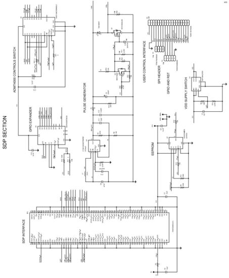 Figure 24. EVAL-ADMT4000SD1Z, SDP Interface Section Schematic
 Figure 25. EVAL-ADMT4000SD1Z, Board Break Off Section Schematic
 Figure 26. EVAL-ADMT4000SD1Z Dimensions, Units Are Millimeters [Inches]
For details on the sensor position within the package, refer to the ADMT4000 data sheet. Referring to the label numbers in Figure 26, Label 1 shows the SDP mounting holes.
The mounting holes sizes are shown in Figure 26 and Table 13.
Table 13. EVAL-ADMT4000SD1Z Mounting Hole Dimensions
| Symbol | Diameter (mm) | Plating |
| A | 2.2 | Nonplated |
| B | 3.175 | Nonplated |
| C | 3.2 | Nonplated |
ORDERING INFORMATION
BILL OF MATERIALS
Table 14. Bill of Materials
| Component | Description | Manufacturer | Part Number |
| C1, C2 | 1 µF ceramic capacitors, 10 V, 5%, X8L, 0805, AEC-Q200 | Kemet | C0805C105J8NACAUTO |
| C3, C8, C13 | 0.1 µF ceramic capacitors, 35 V, 10%, X7R, 0402, AEC-Q200 | TDK | CGA2B3X7R1V104K050BB |
| C4 | LOW ESR | Vishay | MAL216099103E3 |
| 220 µF aluminium electrolytic capacitor, 50 V, 20%, 12.5 mm | |||
| × 16 mm, AEC-Q200, 550 mA | |||
| C5, C7 | 10 µF ceramic capacitors, 6.3 V, 20%, X7R, 0603 | Samsung | CL10B106MQ8NRNC |
| C6, C10, C15, C18, C19 | 0.1 µF ceramic capacitors, 50 V, 10%, X8R, 0603, AEC-Q200 | TDK | CGA3E3X8R1H104K080AB |
| C9 | 4.7 µF ceramic capacitor, 16 V, 5%, X7R, 0805, AEC-Q200 | Kemet | C0805X475J4RACAUTO |
| C11 | 22 pF ceramic capacitor, 100 V, 5%, C0G, 0603, AEC-Q200 | TDK | CGA3E2NP02A220J080AA |
| C12 | 1100 pF ceramic capacitor, 50 V, 1%, X8G, 0603, AEC-Q200 | Murata | GCM1885G1H112FA16D |
| C14 | 0.047 µF ceramic capacitor, 25 V, 10%, X8R, 0402, AEC-Q200, soft termination | TDK | CGA2B1X8R1E473K050BE |
| C16 | 0.047 µF ceramic capacitor, 0.047 µF, 25 V, 10% X8R, 0402, AEC-Q200 |
TDK | CGA2B1X8R1E473K050BE |
| C17 | 2 pF ceramic capacitor, 25 V, 0.1 pF, C0G, 0402 | AXV | 04023U2R0BAT2A |
| D1 | Diode, high conductance fast switching | Fairchild Semiconductor | 1N914BWT |
| DS1, DS2 | Diodes, hyper bright, low current, light emitting diode (LED), green | Osram Opto Semiconductors | LGL29K-G2J1-24-Z |
| L1 | Inductor, wirewound, 15 μH, 10%, 2.52 MHz, 0.6 A, 0.5 Ω, 1812, AEC-Q200 | TDK | B82432T1153K000 |
| P1 | 120-position board to board connector recepticle, 0.6 mm pitch | HR | FX8-120S-SV(21) |
| P3 | 4-position PCB header strip, 0.100″ pitch | Samtec | TSW-104-08-G-S |
| P2 | 5-position PCB header strip, 0.100″ pitch | Samtec | TSW-105-08-G-S |
| P4 | 18-position PCB header strip, 0.100″ pitch | Samtec | TSW-118-16-G-S |
| P5, P6 | 2-position PCB header strips, 0.100″ pitch | Amphenol | 9157-102HLF |
| P7 | 15-position PCB header, right angle 0.100″ pitch | Molex | 53048-1510 |
| Q1 | N-channel MOSFET, 14 A, 50 V, 3-pin DPAK | Onsemi | RFD14N05LSM |
| Q2 | N-channel MOSFET, 200 mA, 50 V, 3-pin SOT-23 | Diodes Incorporated | BSS138-7-F |
| R1 | 1 kΩ SMD resistor, 1%, 1/8 W, 0805, AEC-Q200 | Panasonic | ERJ-6ENF1001V |
| R2 | 0.005 Ω SMD resistor, 1%, 2 W, 2512, wide terminal | Ohmite | LVK25R005FER |
| R3, R6, R17, R20, R21, R25, | 0 Ω SMD resistors, jumper, 1/10 W, 0402, AEC-Q200 | Panasonic | ERJ-2GE0R00X |
| R26 to R28, R31, R4, R9, R12, R16, R19, R29, R30, R34 to R37, R40 to R42 | 100 kΩ SMD resistors, 5%, 1/10 W, 0402, AEC-Q200 | Panasonic | ERJ-2GEJ104X |
| R5, R33 | 1.5 kΩ SMD resistors, 1%, 1/10 W, 0603, AEC-Q200 | Panasonic | ERJ-3EKF1501V |
| R7 | 261 kΩ SMD resistor, 0.1%, 1/8 W, 0805, AEC-Q200 | Panasonic | ERA-6AEB2613V |
| R8 | 10 kΩ SMD resistor, 0.1%, 1/8 W, 0805, AEC-Q200 | Panasonic | ERA-6AEB103V |
| R10, R11, R15, R22 | 4.75 kΩ SMD resistors, 1%, 1/10 W, 0402, AEC-Q200 | Panasonic | ERJ-2RKF4751X |
| R13, R18 | 10 kΩ SMD resistors, 1%, 1/8 W, 0805, AEC-Q200 | Panasonic | ERJ-6ENF1002V |
| R14 | 20 kΩ SMD resistor, 1%, 1/8 W, 0805, AEC-Q200 | Panasonic | ERJ-6ENF2002V |
| R23, R24 | 10 kΩ SMD resistors, 5%, 1/10 W, 0603, AEC-Q200 | Panasonic | ERJ-3GEYJ103V |
| R32 | 0.1 Ω SMD resistor, 1%, 1/6 W, 0402, AEC-Q200 | Panasonic | ERJ-2BSFR10X |
| R38, R39 | 1 MΩ SMD resistors, 1%, 1/10 W, 0603, AEC-Q200 | Panasonic | ERJ-3EKF1004V |
| U1 | True power-on multiturn sensor | Analog Devices | ADMT4000BRUZAB |
| U2 | IC 32 kBIT serial EEPROM | Microchip Technology | 24AA32A-I/SN |
| U3 | 5 V, 3 A logic-controlled high-side power switch | Analog Devices | ADP196ACPZN-R7 |
| U4 | 3 MHz step-up DC/DC converters with integrated Schottky in thin SOT | Analog Devices L | LT3461AES6#TRMPBF |
| U5 | IC expander serial peripheral interface (SPI), general-purpose input and output (GPIO), 8 bit | Microchip Technology | MCP23S08T-E/SS |
| U6 | CMOS, low voltage, SPI/QSPI/Microwire-compatible interface, serially controlled, octal SPST switches |
Analog Devices | ADG714BCPZ-REEL7 |
![]() ESD Caution
ESD Caution
ESD (electrostatic discharge) sensitive device. Charged devices and circuit boards can discharge without detection. Although this product features patented or proprietary protection circuitry, damage may occur on devices subjected to high energy ESD. Therefore, proper ESD precautions should be taken to avoid performance degradation or loss of functionality.
Legal Terms and Conditions
By using the evaluation board discussed herein (together with any tools, components documentation or support materials, the “Evaluation Board”), you are agreeing to be bound by the terms and conditions set forth below (“Agreement”) unless you have purchased the Evaluation Board, in which case the Analog Devices Standard Terms and Conditions of Sale shall govern. Do not use the Evaluation Board until you have read and agreed to the Agreement. Your use of the Evaluation Board shall signify your acceptance of the Agreement. This Agreement is made by and between you (“Customer”) and Analog Devices, Inc. (“ADI”), with its principal place of business at Subject to the terms and conditions of the Agreement, ADI hereby grants to Customer a free, limited, personal, temporary, non-exclusive, non-sublicensable, non-transferable license to use the Evaluation Board FOR EVALUATION PURPOSES ONLY. Customer understands and agrees that the Evaluation Board is provided for the sole and exclusive purpose referenced above, and agrees not to use the Evaluation Board for any other purpose. Furthermore, the license granted is expressly made subject to the following additional limitations: Customer shall not (i) rent, lease, display, sell, transfer, assign, sublicense, or distribute the Evaluation Board; and (ii) permit any Third Party to access the Evaluation Board. As used herein, the term “Third Party” includes any entity other than ADI, Customer, their employees, affiliates and in-house consultants. The Evaluation Board is NOT sold to Customer; all rights not expressly granted herein, including ownership of the Evaluation Board, are reserved by ADI. CONFIDENTIALITY. This Agreement and the Evaluation Board shall all be considered the confidential and proprietary information of ADI. Customer may not disclose or transfer any portion of the Evaluation Board to any other party for any reason. Upon discontinuation of use of the Evaluation Board or termination of this Agreement, Customer agrees to promptly return the Evaluation Board to ADI. ADDITIONAL RESTRICTIONS. Customer may not disassemble, decompile or reverse engineer chips on the Evaluation Board. Customer shall inform ADI of any occurred damages or any modifications or alterations it makes to the Evaluation Board, including but not limited to soldering or any other activity that affects the material content of the Evaluation Board. Modifications to the Evaluation Board must comply with applicable law, including but not limited to the RoHS Directive. TERMINATION. ADI may terminate this Agreement at any time upon giving written notice to Customer. Customer agrees to return to ADI the Evaluation Board at that time. LIMITATION OF LIABILITY. THE EVALUATION BOARD PROVIDED HEREUNDER IS PROVIDED “AS IS” AND ADI MAKES NO WARRANTIES OR REPRESENTATIONS OF ANY KIND WITH RESPECT TO IT. ADI SPECIFICALLY DISCLAIMS ANY REPRESENTATIONS, ENDORSEMENTS, GUARANTEES, OR WARRANTIES, EXPRESS OR IMPLIED, RELATED TO THE EVALUATION BOARD INCLUDING, BUT NOT LIMITED TO, THE IMPLIED WARRANTY OF MERCHANTABILITY, TITLE, FITNESS FOR A PARTICULAR PURPOSE OR NONINFRINGEMENT OF INTELLECTUAL PROPERTY RIGHTS. IN NO EVENT WILL ADI AND ITS LICENSORS BE LIABLE FOR ANY INCIDENTAL, SPECIAL, INDIRECT, OR CONSEQUENTIAL DAMAGES RESULTING FROM CUSTOMER’S POSSESSION OR USE OF THE EVALUATION BOARD, INCLUDING BUT NOT LIMITED TO LOST PROFITS, DELAY COSTS, LABOR COSTS OR LOSS OF GOODWILL. ADI’S TOTAL LIABILITY FROM ANY AND ALL CAUSES SHALL BE LIMITED TO THE AMOUNT OF ONE HUNDRED US DOLLARS ($100.00). EXPORT. Customer agrees that it will not directly or indirectly export the Evaluation Board to another country, and that it will comply with all applicable United States federal laws and regulations relating to exports. GOVERNING LAW. This Agreement shall be governed by and construed in accordance with the substantive laws of the Commonwealth of Massachusetts (excluding conflict of law rules). Any legal action regarding this Agreement will be heard in the state or federal courts having jurisdiction in Suffolk County, Massachusetts, and Customer hereby submits to the personal jurisdiction and venue of such courts. The United Nations Convention on Contracts for the International Sale of Goods shall not apply to this Agreement and is expressly disclaimed.
![]() ©2024 Analog Devices, Inc. All rights reserved.
©2024 Analog Devices, Inc. All rights reserved.
Trademarks and registered trademarks are the property of their respective owners.
One Analog Way, Wilmington, MA 01887-2356, U.S.A.
Documents / Resources
 |
ANALOG DEVICES ADMT4000 True Power On Multi Turn Position Sensor [pdf] User Guide ADMT4000 True Power On Multi Turn Position Sensor, ADMT4000, True Power On Multi Turn Position Sensor, Power On Multi Turn Position Sensor, On Multi Turn Position Sensor, Multi Turn Position Sensor, Position Sensor, Sensor |