![]()
Evaluation Board User Guide
ADA4620-1
Evaluating the ADA4620-1 36 V, Precision, Low Noise, 16.5 MHz JFET Op Amp
Features
- Full-featured evaluation board for the ADA4620-1
- Enables quick prototyping
- Provisions for user-defined circuit configuration
- Footprint provision for a photodiode for rapid evaluation
- Edge-mounted connectors and test point provisions
General Description
The EVAL-ADA4620-1ARZ is an evaluation board designed for the ADA4620-1, a 36 V, precision, low noise, low offset drift, JFET op amp, available in an 8-lead SOIC package. The ADA4620-1 is preconfigured on this board as a unity-gain follower buffer. This four-layer evaluation board includes edge-mounted subminiature version A (SMA) connectors on both the inputs and output, facilitating efficient connections to the test and measurement equipment or external circuits.
The evaluation board’s ground plane, component placement, and power supply decoupling are optimized for maximum circuit flexibility and performance. Additionally, the evaluation board features a variety of unpopulated resistor and capacitor pads, offering multiple choices and extensive flexibility for various application circuits and configurations, such as active loop filter, transimpedance amplifier (TIA), and charge amplifier. Furthermore, a combination of test points and edge-mounted SMA connectors are utilized for inputs, output, and signal measurements.
The evaluation board includes provisions for photodiode footprint, facilitating easy configuration of a TIA. Additionally, the evaluation board offers provisions for constructing various types of filters. To select specific component values and design filters, refer to
https://tools.analog.com/en/filterwizard.
The ADA4620-1 data sheet covers the specifications, details of device operation, and application circuit configurations and guidance. Consult the data sheet with this user guide for a better understanding of the device operation, especially when powering up the evaluation board for the first time.
Evaluation Board Quick Start Operation
Overview
The following sections outline the basic prepopulated configuration of the EVAL-ADA4620-1ARZ required to test the basic functionality of the ADA4620-1. The board has provisions to make it highly configurable for many applications. The connectors on the board provide an easy interface to various bench equipment.
Equipment Needed
- A signal generator
- A dual output DC power supply
- An oscilloscope
Amplifier Configuration
The EVAL-ADA4620-1ARZ board is configured in a noninverting configuration with a default gain of +1. Preinstalled resistors accommodate this configuration.
Power Supply Connection
The terminal turret connectors, designated by VS+, VS−, and GND, power the evaluation board. Connect the DC power with the correct polarity and voltage. Reversing the polarity or applying overvoltage can permanently damage the evaluation board. Permissible supply voltages range from 4.5 V to 36 V for single supply configuration and from ±2.25 V to ±18 V for dual supply configuration. Applying higher voltages may damage the amplifier. Decoupling capacitors of 10 µF and 0.1 µF come preinstalled on the board for immediate operation.
Board Evaluation Connections
For initial evaluation, use the following connection procedure:
- Ensure the power supply is off. Connect the positive supply, negative supply, and ground to the terminal turret connectors labeled VS+, VS−, and GND, respectively.
- Ensure the signal generator output is disabled. Connect the signal source to IN+ or test point TP_IN+ and set the signal source to high impedance (high Z) output.
- Connect the output SMA connector (VO) to the oscilloscope.
Power-Up Procedure
Follow this procedure to power up the board once the connection process (as discussed in the previous section) is complete. Figure 1 illustrates the necessary connections.
- Set the V+ supply to +15 V and the V− supply to −15 V.
- Turn on the power supply. The typical supply current of the ADA4620-1 is 1.3 mA.
- Configure the signal source to output a 10 kHz sine wave with a 5 V peak-to-peak amplitude with 0 V DC offset.
- Enable the signal source. The oscilloscope must show a 5 V peak-to-peak sine wave at the output with the same frequency of the input signal.
Transimpedance Amplifier (TIA) Configuration
The low input bias current and low input capacitance of the ADA4620-1 amplifier make it a good choice for transimpedance configurations. The evaluation board has an onboard provision for a photodiode (radial package).
When operating in a TIA configuration, a bias voltage can be applied to the VPD test point to bias the anode of the photodiode. If no bias voltage needs to be applied, install a 0 Ω resistor at the R5 footprint. For this TIA configuration, install the photodiode at the PD footprint and connect a feedback resistor at the RF1 footprint. A feedback capacitor at the CF1 footprint can be added for stability of the circuit.
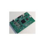
EV Kit Photo


ADA4620-1 EV Schematic

ADA4620-1 EV PCB Layout


Revision History
| REVISION NUMBER | REVISION DATE | DESCRIPTION | PAGES CHANGED |
| 0 | 24-Oct | Initial release | — |
ALL INFORMATION CONTAINED HEREIN IS PROVIDED “AS IS” WITHOUT REPRESENTATION OR WARRANTY. NO RESPONSIBILITY IS ASSUMED BY ANALOG DEVICES FOR ITS USE, NOR FOR ANY INFRINGEMENTS OF PATENTS OR OTHER RIGHTS OF THIRD PARTIES THAT MAY RESULT FROM ITS USE. SPECIFICATIONS ARE SUBJECT TO CHANGE WITHOUT NOTICE. NO LICENSE, EITHER EXPRESSED OR IMPLIED, IS GRANTED UNDER ANY ADI PATENT RIGHT, COPYRIGHT, MASK WORK RIGHT, OR ANY OTHER ADI INTELLECTUAL PROPERTY RIGHT RELATING TO ANY COMBINATION, MACHINE, OR PROCESS, IN WHICH ADI PRODUCTS OR SERVICES ARE USED. TRADEMARKS AND REGISTERED TRADEMARKS ARE THE PROPERTY OF THEIR RESPECTIVE OWNERS. ALL ANALOG DEVICES PRODUCTS CONTAINED HEREIN ARE SUBJECT TO RELEASE AND AVAILABILITY.
Documents / Resources
 |
ANALOG DEVICES ADA4620-1 Evaluation Board [pdf] User Guide EVAL-ADA4620-1ARZ, ADA4620-1 Evaluation Board, ADA4620-1, Evaluation Board, Board |