AMC C 5/ C 30/ C 60 Volume Controls

WIRING DIAGRAM
- Connect volume controllers according wiring diagrams below. Select requested mode: passive or active .
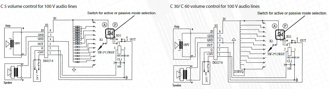
P. Passive mode: C X attenuates the volume if 24 V is not connected to 24 V terminal. After the voltage supplying, C X sets the maximum volume level.
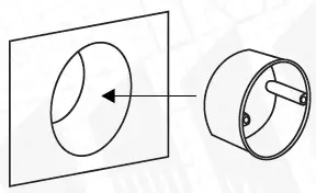
A. Active mode: C X set the maximum volume level if 24 V is not connected to 24 V terminal. After the voltage supplying, C X starts attenuate volume. - Install flush mount box into the wall. Please note – controllers will fit well only with AMC flush mount wall boxes. There are two type of boxes: for drywalls – CBh, for solid walls – CBs. Items can be purchased optionally.
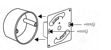
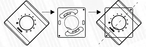
- Mount controller into the box and tighten the screws.
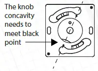
- Turn rotary switch counterclockwise till it stops to min position. Put the knob on the volume controller. Pay attention to knob concavity. The knob concavity should be in the middle with a black dot as shown in the picture below.
- Keep a plastic top panel in a 45˚ position and mount it on the volume controller. For easy orientation black dot marking should align with AMC letters as shown in picture below.
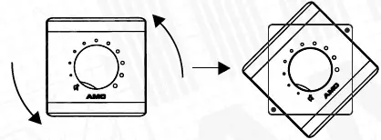
- Turn counterclockwise until it clicks and locks into place.
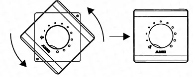
- To remove pull it and turn it counterclockwise. Take off the cover.
Documents / Resources
 |
AMC C 5/ C 30/ C 60 Volume Controls [pdf] Installation Guide C 5 Volume Controls, C 30 Volume Controls, C 60 Volume Controls, Volume Controls |