alpscontrols PR066X Intuitive Controller Expansion Boards
Intuitive Expansion Boards
Description
The Intuitive Expansion boards, detailed below, are intended for use with either the Intuitive controller (PR0650) or the DMTouch with a CANbus network interface. The expansion boards allow for additional inputs and outputs to expand upon the parent device’s operation and functionality (such as TDB, Super Pack, CO2 or Circuit Control). A single Intuitive controller or DMTouch can have up to 10 expansion boards connected at any one time. The expansion boards have an in-built CANbus interface which allows for networking to the master device. All IO connectors are plug and socket and all within a small footprint which is panel or DIN rail mountable. A DIN mount, 24V 2A PSU (PR0625) is available for use with the expansion boards.
| Intuitive Expansion Board Descriptions | Part Number |
| Intuitive Stepper with 8 Probe Inputs, 8 Status Inputs, 8 Universal I/O, 4 Relay Outputs and 6 Stepper Motor outputs. | PR0660 |
| Intuitive IO Expansion Board with 8 Probe Inputs, 8 Status Inputs, 8 Universal I/Os and 12 Relay Outputs | PR0661 |
| Intuitive 48 Probe Input Expansion Board with 8 Universal I/Os and 48 Probe Inputs | PR0662 |
| Mini Intuitive IO expansion module with 4 analogue inputs (mA/V) and 5 Relay Outputs | PR0663 |
| Mini Intuitive IO expansion module with 4 Universal IO (mA/V) and 4 Relay Outputs | PR0663 4-4 |
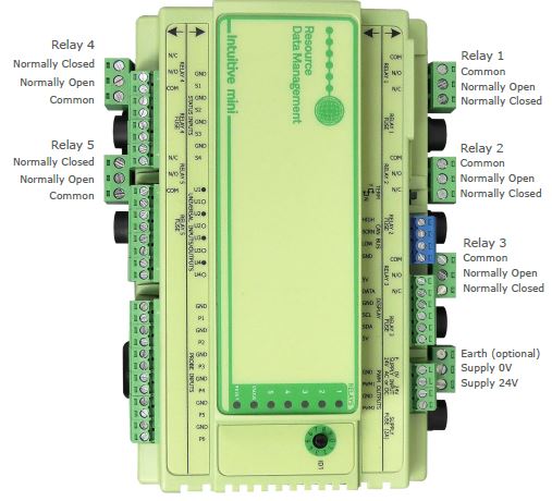
| Mini Intuitive IO expansion module with 4 Universal IO (mA/V), 5 Relay Outputs, 6 Probe Inputs, 4 Status Inputs and 2 PWM Outputs. | PR0681 |
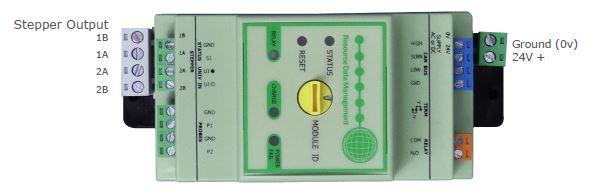
| Intuitive Stepper Module with Auto Close – 1 Stepper Motor Output, 1 Analogue Input (mA/V), 2 probe Inputs, 1 Digital Input & 1 Relay output | PR0653 |
| Intuitive Stepper Module with Auto Close – 1 Stepper Motor Output, 1 Analogue Input (mA/V), 2 probe Inputs, 1 Digital Input & 1 Relay output. Valve closes on CANbus communication failure. |
PR0653-C |
| CANbus network cable (Per Meter) | PR0649 |
Configuration
The expansion boards have no configuration until they have been configured in the master device to which they are connected. Please see the relevant documentation for their setup.
Networks
The expansion boards have a built-in CANbus network interface that allows for connection to the Intuitive, DMTouch or another expansion board. For it to communicate successfully the Module ID rotary switch must be set to the desired address on each expansion board. Please refer to the Intuitive Controller user document
(TDB for example) with regards to mapping the Expansion boards.
Connecting to the controller
The master device (Intuitive or DMTouch) allows for the utilisation of an expansion board’s inputs and outputs. The status of each input and output can be viewed from the main device’s web pages. The expansion boards cannot be viewed directly.
Expansion Board Wiring Connections
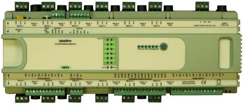
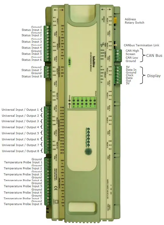
PR0660 Intuitive Stepper Expansion Board Wiring Connections
PR0660
Bottom Row
Connections
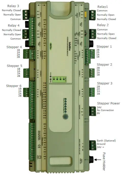
PR0660
Top Row
Connections

PR0661 Intuitive IO Expansion Board Wiring Connections
PR0661
Bottom Row
Connections
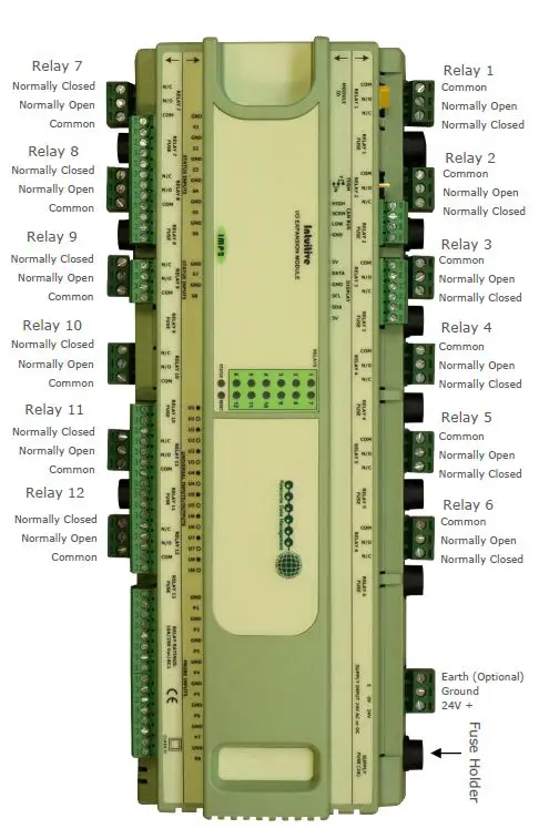
PR0661
Top Row
Connections
PR0662 Intuitive 48 Input Expansion Board Wiring Connections
PR0662
Connections

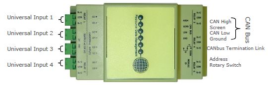
PR0663 Mini Intuitive IO Expansion Module Wiring Connections
PR0663
Top Row
Connections
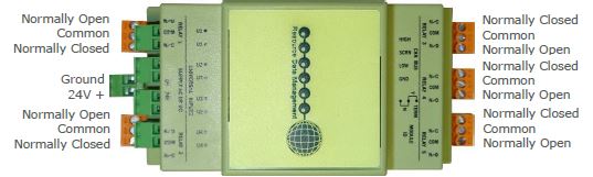
PR0663
Bottom Row
Connections
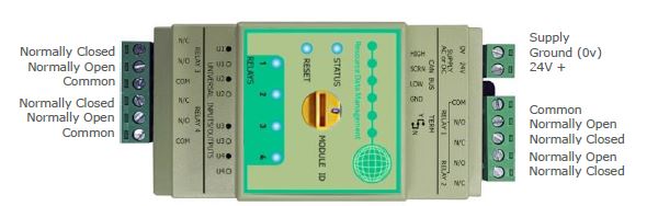
PR0663 4-4 Mini Intuitive IO 4-4 Expansion Module Wiring Connections
PR0663 4-4
Top Row
Connections

PR0663 4-4
Bottom Row
Connections
PR0681 Mini Intuitive IO Expansion Module Wiring Connections
PR0681
Top Row
Connections
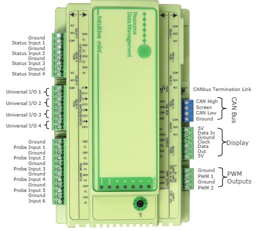
PR0681
Top Bottom
Connections
PR0653 Intuitive Stepper Module with Auto Close Wiring Connections
PR0653
PR0653-C
Top Row
Connections
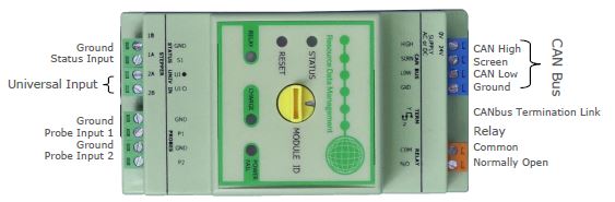
PR0653
PR0653-C
Bottom Row
Connections
The module contains an internal back-up power supply based on Electric Double-Layer Capacitor (supercapacitor) technology that is used to close the valve when a power fail is detected. The module will run as configured in TDB until power to the module is interrupted – at which point the module internally detects this power failure and initiates an emergency closure of the valve. A list of valves that can be configured to utilise this feature is provided within the Technical specification. In the event of CANbus communication being lost with the main controller, after 1 minute the PR0653 will set the valve position to the last hour average opening position while the PR0653-C will shut the valve fully until communications are re-established.
Intuitive Expansion Boards Universal Input / Output Connections
| Universal IO Type Configured | Terminal Markings |
| 4-20mA Input | Sig In 12Vdc Out |
| 0-10V Input | Ground Sig In |
| 4-20mA Output | Ground Sig Out |
| 0-10V Output | Ground Sig Out |
Note: the PR0663 Mini IO expansion board and the PR0653 Stepper Module with Auto-Close only has Universal Analogue Inputs. They cannot be used as Analogue Outputs.
Technical Specifications
Stepper Expansion Board (PR0660)
| Power Requirements | |
| Supply Voltage Range | 24VDC ±10% or 24VAC ±10% |
| Supply Frequency | DC or 50-60Hz ±10% |
| Maximum Supply Current | 1.5A (Not Including Stepper Power) |
| Typical Supply Current | <1A (Not Including Stepper Power) |
| General | |
| Operating Temperature Range | -40°C to +60°C (-40°F to +140°F) |
| Operating Humidity | 80% Maximum |
| Storage Temperature Range | -40°C to +65°C (-40°F to +149°F) |
| Environmental | Indoor use at altitudes up to 2000m, pollution degree 2, installation category II. |
| Dimensions – L x W x H | 280mm (11in) x 122mm (4.8in) x 67mm (2.6in) |
| Safety | EN 61010-1:2010 |
| IP Rating | IP20 |
| EMC | EN 61326-1:2013
FCC CFR 47 Parts 15.107 & 15.109 and ICES-003 Issue 6 |
| Ventilation | There is no requirement for forced cooling ventilation |
| Class 2 Insulation | No protective Earth is required. A functional Earth may be fitted in noisy environments. |
| Supply Fuse | Built-In: 2A 240VAC Anti Surge (T) HRC conforming to IEC60127, 32×6.3mm |
| External MCB | 2A 240VAC Type D conforming to BS EN 60898 |
| Relays | |
| Max Current | 10A Resistive Load (cos θ = 1) |
| Max Voltage | 250VAC, 24VDC |
| Built-In Relay Fuse | 10A 240Vac Anti Surge (T) HRC conforming to IEC60127, 32×6.3mm |
|
Relay Spacing |
Relays 1 & 2 must together be either mains or low voltage.
Relays 3 & 4 independently allow the use of mains or low voltage on either relay. |
| PWM Outputs | |
| Frequency Range | 0.016667Hz – 20kHz |
| Period Limits | Min: 50µs Max: 60s |
| Period Resolution | 10µs |
| Duty Cycle Range | 0 – 100% |
| Internal Pull-Up Enabled | High-Level Output Voltage: Typical 4.7V ± 200mV
(recommended minimum 10kΩ load impedance) |
| Internal Pull-Up Disabled | External Voltage Range: 1V – 30V DC Maximum Current Sinking: 75mA |
| Inputs / Outputs | |
| Digital Inputs 1-8 | 0V return or 24 Vac **See Note 1 |
| Analogue Inputs 1-8 | Temperature Probe input ** See note 2 |
| Universal IO 1-8 | Analogue Input or Output ** See note 3 |
| Relays 1-4 | N/O, N/C and Common – Volt Free |
|
Steppers 1-6 |
Out1B, Out1A, Out2A and Out2B
Chopper current drive suitable for Bipolar (4-Wire) and Unipolar (6/8- Wire) stepper valves Max Valve Motor Power 8W Max Phase Current 580mArms / 825mA peak |
|
Stepper Power* |
V1, No Connection (N/C) and V2 – An external AC or DC supply is required to operate the stepper output drives.*.
Maximum supply current 5A |
| Module ID | Position 0 through to 9 – Select a unique ID for each expansion board in use** |
| Display | Not Currently Used |
| Status LED | Healthy LED – When powered up the LED will flash off/on every 0.5 seconds. |
I/O Expansion Board (PR0661)
| Power Requirements | |
| Supply Voltage Range | 24VDC ±10% or 24VAC ±10% |
| Supply Frequency | DC or 50-60Hz ±10% |
| Maximum Supply Current | 1.5A |
| Typical Supply Current | <1A |
| General | |
| Operating Temperature Range | Without SSR fitted : -40°C to +60°C (-40°F to +140°F) With SRR fitted: -20°C to +60°C (-4°F to +140°F) |
| Operating Humidity | 80% Maximum |
| Storage Temperature Range | Without SSR fitted: -40°C to +65°C (-40°F to +149°F) With SSR fitted : -30°C to +65°C (-22°F to +149°F) |
| Environmental | Indoor use at altitudes up to 2000m, pollution degree 2, installation category II. |
| Dimensions – L x W x H | 280mm (11in) x 122mm (4.8in) x 67mm (2.6in) |
| Safety | EN 61010-1:2010 |
| IP Rating | IP20 |
| EMC | EN 61326-1:2013
FCC CFR 47 Parts 15.107 & 15.109 and ICES-003 Issue 6 |
| Ventilation | There is no requirement for forced cooling ventilation |
| Class 2 Insulation | No protective Earth is required. A functional Earth may be fitted in noisy environments. |
| Supply Fuse | Built-In: 2A 240VAC Anti Surge (T) HRC conforming to IEC60127, 32×6.3mm |
| External MCB | 2A 240VAC Type D conforming to BS EN 60898 |
| Mechanical Relays | |
| Max Current | 10A Resistive Load (cos θ = 1) |
| Max Voltage | 250VAC, 24VDC |
| Built-In Relay Fuse | 10A 240Vac Anti Surge (T) HRC conforming to IEC60127, 32×6.3mm |
|
Relay Spacing |
Relays 1-6 must together be either all mains or all low voltage. Relays 7-12 independently allow the use of mains or low voltage on any relay. |
| Solid State Relays | |
| Max Current | 1Arms (1A Fuse if Applicable) |
| Voltage | 12-280VAC (Not DC Voltage Compatible) |
| PWM Outputs | |
| Frequency Range | 0.016667Hz – 20kHz |
| Period Limits | Min: 50µs Max: 60s |
| Period Resolution | 10µs |
| Duty Cycle Range | 0 – 100% |
| Internal Pull-Up Enabled | High-Level Output Voltage: Typical 4.7V ± 200mV
(recommended minimum 10kΩ load impedance) |
| Internal Pull-Up Disabled | External Voltage Range: 1V – 30V DC Maximum Current Sinking: 75mA |
| Inputs / Outputs | |
| Digital Inputs 1-8 | 0V return or 24 Vac **See Note 1 |
| Analogue Inputs 1-8 | Temperature Probe input ** See note 2 |
| Universal IO 1-8 | Analogue Input or Output ** See note 3 |
| Relays 1-12 | N/O, N/C and Common – – Volt Free |
| Module ID | Position 0 through to 9 – Select a unique ID for each expansion board in use** |
| Display | Not Currently Used |
| Status LED | Healthy LED – When powered up the LED will flash off/on every
0.5 seconds. |
48 Input Expansion Board (PR0662
| Power Requirements | |
| Supply Voltage Range | 24VDC ±10% or 24VAC ±10% |
| Supply Frequency | DC or 50-60Hz ±10% |
| Maximum Supply Current | 1.5A |
| Typical Supply Current | <1A |
| General | |
| Operating Temperature Range | -40°C to +60°C (-40°F to +140°F) |
| Operating Humidity | 80% Maximum |
| Storage Temperature Range | -40°C to +65°C (-40°F to +149°F) |
| Environmental | Indoor use at altitudes up to 2000m, pollution degree 2, installation category II. |
| Dimensions – L x W x H | 280mm (11in) x 122mm (4.8in) x 67mm (2.6in) |
| Safety | EN 61010-1:2010 |
| IP Rating | IP20 |
| EMC | EN 61326-1:2013
FCC CFR 47 Parts 15.107 & 15.109 and ICES-003 Issue 6 |
| Ventilation | There is no requirement for forced cooling ventilation |
| Class 2 Insulation | No protective Earth is required. A functional Earth may be fitted in noisy environments. |
| Supply Fuse | Built-In: 2A 240VAC Anti Surge (T) HRC conforming to IEC60127, 32×6.3mm |
| External MCB | 2A 240VAC Type D conforming to BS EN 60898 |
| Inputs / Output | |
| Analogue Inputs 1-48 | Temperature Probe input ** See note 2 |
| Universal IO 1-8 | Analogue Input or Output ** See note 3 |
| Module ID | Position 0 through to 9 – Select a unique ID for each expansion board in use** |
| Display | Not Currently Used |
| Status LED | Healthy LED – When powered up the LED will flash off/on every
0.5 seconds. |
Mini IO Expansion Module (PR0663 / PR0663 4-4)
| Power Requirements | |
| Supply Voltage Range | 24VDC ±10% or 24VAC ±10% |
| Supply Frequency | DC or 50-60Hz ±10% |
| Maximum Supply Current | 0.25A |
| Typical Supply Current | <0.15A |
| General | |
| Operating Temperature Range | Without SSR Fitted: -40°C to +60°C (-40°F to +140°F) With SRR fitted: -30°C to +60°C (-22°F to +140°F) |
| Operating Humidity | 80% Maximum |
| Storage Temperature Range | Without SSR Fitted : -40°C to +65°C (-40°F to +149°F) With SSR fitted : -30°C to +65°C (-22°F to +149°F) |
| Environmental | Indoor use at altitudes up to 2000m, pollution degree 2, installation category II. |
| Dimensions – L x W x H | 52.5mm (2in) x 134mm (5.2in) x 70mm (2.8in) |
| Safety | EN 61010-1:2010, UL 62368-1 |
| IP Rating | IP20 |
| EMC | EN 61326-1:2013
FCC CFR 47 Parts 15.107 & 15.109 and ICES-003 Issue 6 |
| Ventilation | There is no requirement for forced cooling ventilation |
| Class 2 Insulation | No protective Earth is required. |
| External Supply Fuse | 2A 240VAC Anti Surge (T) HRC conforming to IEC60127, 32×6.3mm |
| External MCB | 2A 240VAC Type D conforming to BS EN 60898 |
| Mechanical Relays | |
| Max Load Current | 5A Resistive (cos θ = 1) |
| Max Load Voltage | 250VAC, 30VDC |
| Relay Spacing | Relays 1 & 2 must together be either mains or low voltage. Relays 3 & 4 must together be either mains or low voltage. |
| Solid State Relays (factory fitted option) | |
| Max Load Current | 1Arms |
| Min Load Current | 0.025Arms |
| Load Voltage Range | 20-280VAC (Not DC Voltage Compatible) |
| Inputs / Outputs | |
| Universal Inputs 1-4 | Analogue Input or Output ** See note 3 |
| Relays 1-5 | N/O, N/C and Common – Volt Free |
| Module ID | Position 0 through to 9 – Select a unique ID for each expansion board in use** |
Mini IO Expansion Module (PR0681)
| Power Requirements | |
| Supply Voltage Range | 24VDC ±10% or 24VAC ±10% |
| Supply Frequency | DC or 50-60Hz ±10% |
| Maximum Supply Current | 1.0A |
| Typical Supply Current | <0.25A |
| General | |
| Operating Temperature Range | Without SSR Fitted: -40°C to +60°C (-40°F to +140°F) With SRR fitted: -30°C to +60°C (-22°F to +140°F) |
| Operating Humidity | 80% Maximum |
| Storage Temperature Range | Without SSR Fitted : -40°C to +65°C (-40°F to +149°F) With SSR fitted : -30°C to +65°C (-22°F to +149°F) |
| Environmental | Indoor use at altitudes up to 2000m, pollution degree 2, installation category II. |
| Dimensions – L x W x H | 101mm (3.87”) x 157mm (6.18”) x 67mm (2.63”) |
| Safety | EN 61010-1:2010, UL 62368-1 |
| IP Rating | IP20 |
| EMC | EN 61326-1:2013
FCC CFR 47 Parts 15.107 & 15.109 and ICES-003 Issue 6 |
| Ventilation | There is no requirement for forced cooling ventilation |
| Class 2 Insulation | No protective Earth is required. |
| External Supply Fuse | 2A 240VAC Anti Surge (T) HRC conforming to IEC60127, 32×6.3mm |
| External MCB | 2A 240VAC Type D conforming to BS EN 60898 |
| Mechanical Relays | |
| Max Load Current | 5A Resistive (cos θ = 1) |
| Max Load Voltage | 250VAC, 30VDC |
| Relay Spacing | Relays 1 & 2 must together be either mains or low voltage. Relays 3 & 4 must together be either mains or low voltage. |
| Solid State Relays (factory fitted option) | |
| Max Load Current | 1Arms |
| Min Load Current | 0.025Arms |
| Load Voltage Range | 20-280VAC (Not DC Voltage Compatible) |
| Inputs/Outputs | |
| Analogue Input or Output | See note 3 |
| Module ID | Position 0 through to 9, elect a unique ID for each expansion board in use** |
| Digital Inputs 1-4 | 0V return or 24 Vac, See note 1 |
| Probe Inputs 1 to 6 | Temperature Probe/Plant input, configurable in application software. |
| PWM Outputs 1 to 2 | Pulse Width Modulation Output (PWM) for use with TDB software only. |
Intuitive Stepper Module with Auto Close (PR0653 / PR0653-C)
| Power Requirements | |||||||
| Supply Voltage Range | 24VDC ±10% or 24VAC ±10% | ||||||
| Supply Frequency | DC or 50-60Hz ±10% | ||||||
| Maximum Supply Current | 0.3A (Not Including Stepper Current) | ||||||
| Typical Supply Current | <0.15A (Not Including Stepper Current) | ||||||
| Maximum Supply Current | 1A (Running 8W Stepper Valve at 24VDC) | ||||||
| General | |||||||
| Operating Temperature Range | 0°C to +50°C (32°F to +122°F) | ||||||
| Operating Humidity | 80% Maximum | ||||||
| Storage Temperature Range | 0°C to +65°C (32°F to +149°F) | ||||||
| Environmental | Indoor use at altitudes up to 2000m, pollution degree 2, installation category II. | ||||||
| Dimensions – L x W x H | 52.5mm (2in) x 134mm (5.2in) x 70mm (2.8in) | ||||||
| Approx. Mass | 165g | ||||||
| Safety | EN 61010-1:2010
UL 62368-1 (Not yet Certified) |
||||||
| IP Rating | IP20 | ||||||
|
EMC |
EN 61326-1:2013
FCC CFR 47 Parts 15.107 & 15.109 ICES-003 Issue 6 |
||||||
| Ventilation | There is no requirement for forced cooling ventilation | ||||||
| Insulation | Class III. No protective Earth is required. | ||||||
| External Supply Fuse | 2A Anti Surge (T) HRC conforming to IEC60127 | ||||||
| External Supply MCB | 2A Type D conforming to BS EN 60898 | ||||||
| Mechanical Relay | |||||||
| Max Contact Current | 3A (cos θ = 1) 2A (cos θ = 0.6) | ||||||
| Max Contact Voltage | 250VAC, 30VDC | ||||||
| Stepper Output | |||||||
| Chopper current drive suitable for Bipolar (4-Wire) and Unipolar (6/8-Wire) stepper valves | |||||||
| Max Valve Motor Power | 8W | ||||||
| Max Phase Current | 580mArms / 825mA peak | ||||||
| Valve Closure Power Reserve | |||||||
| Maximum Charge Time | 450 seconds (7min 30sec) | ||||||
| Typical Charge Time | 380 seconds (6min 20sec) | ||||||
| · Charge times apply to supercapacitors that have been completely discharged.
· A full valve closure is possible even if the module is not completely charged depending on the valves energy usage. · The relay output is controlled using TDB under normal operating conditions however if a power fail is detected the relay is de-energised. This allows the relay to function as a power fail alarm by being set permanently on in TDB until a power fail overrides this and disables it. |
|||||||
| LED Functions | |||||||
| Status | Flash green when module is active. | ||||||
| Reset | Solid red when module is in reset. | ||||||
| Relay | Solid blue when relay is energized. | ||||||
|
Charge |
Flash green when module is charging – pulse length proportional to charge level.
Solid green when module is charged. |
||||||
| Power Fail | Flash red when power to the module has been interrupted. | ||||||
| Guaranteed Closure Valve list | |||||||
| ALCO | EX4 | EX5 | EX6 | ||||
| SPORLAN | SEI 0.5-11 | SEI 30/50 | SHE 100/175 | SER 1.5-20 | SER G/J/K | SER AA/A/B/C/D | |
| DANFOSS | ETS 12.5-25B | ETS 50B | ETS 100B | ETS 250/400 | |||
| CAREL | E2/5/6V | E3/4/7V | |||||
| Note: guaranteed valve closure subject to configuration of valve parameters | |||||||
Note
- 24 Vac must have the same 24 Vac return as the supply voltage. If using the Plant controller 24V power supply only the 24Vac signal from the supply is required for the digital input. If using an external 24V power supply to signal a status change then both a common (0V) and status input signal (24V) is required for the appropriate digital input.
- A variety of probes can be used by the Data Builder Analogue block or a custom probe curve can be programmed.
- The Universal Inputs/Outputs are configured through the Plant controller TDB software. Each universal
IO can be set as either:- 0-10 Volts DC Input or
- 0-10 Volts DC Output or
- 4-20ma Output or
- 4-20mA Input (4-20mA current loop, use the 12 Vdc output to feed the 4-20mA device.)
- *Important
- If a 24v AC supply is used to power the stepper expansion board, the same AC supply cannot be used to power the stepper valve, the stepper valve requires its own separate power supply.
- If a 24V DC supply is used however, it can be used to power both the stepper expansion board and the stepper valve.
- If using an Intuitive TDB, rotary switch position 1 refers to board 1. If using Intuitive Pack (SUP, CO2 etc.) rotary switch position 0 refers to board 1. Please refer to the appropriate controller user guide with regards to mapping the available inputs/ outputs on a desired expansion board to a Plant controller.
To meet UL (Underwriters Laboratories) compliance, the equipment must be powered by external power supply or power source via terminal connectors which circuits shall be compliant with the requirements of ES1 and PS2 (LPS) circuits.
Installation
Mounting on to a DIN rail.
The Intuitive controller has two or three DIN rail mounting feet which can slide in and out to three different positions, sliding into each position is accompanied by a “click” which locks the foot into that position.
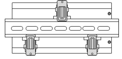
To install the controller onto a DIN mounting rail, from the fully pushed in position slide the top mounting foot out by 2 clicks so that the foot is clear of the DIN rail channel. Slide the bottom two feet out by one click so that they are protruding slightly into the DIN rail channel. The controller can now be inserted onto the DIN rail by inserting the bottom lip of the DIN rail behind the two bottom mounting feet.
The controller can now be pushed flat onto the DIN rail and the top foot pushed in 2 clicks to hold the controller in place. Finally, push the bottom foot (or feet) in by one click to secure the controller.
The mounting feet also have M3 holes for direct mounting where DIN rail is not being used.
Please ensure all power is switched off before installing or maintaining this product.
Group Offices
RDM Group Head Office
80 Johnstone Avenue
Hillington Industrial Estate
Glasgow
G52 4NZ
United Kingdom
+44 (0)141 810 2828
support@resourcedm.com
RDM USA
9441 Science Center Drive
New Hope
Minneapolis
MN 55428
United States
+1 612 354 3923
usasupport@resourcedm.com
RDM Asia
Sky Park at One City
Jalan USJ 25/1
47650 Subang Jaya
Selangor
Malaysia
+603 5022 3188
asiatech@resourcedm.com
Visit www.resourcedm.com/support for more information on RDM solutions, additional product documentation and software downloads.
While every effort is made to ensure the information given within this document is accurate, Resource Data Management Ltd shall not be liable for errors or omissions, for incidental or consequential damages, directly or indirectly, in connection with the furnishing, performance or misuse of this product or document. All specifications are subject to change without notice. See www.resourcedm.com for terms and conditions of sales.
Copyright © Resource Data Management
Documents / Resources
 |
alpscontrols PR066X Intuitive Controller Expansion Boards [pdf] User Guide PR066X Intuitive Controller Expansion Boards, PR066X, Intuitive Controller Expansion Boards, Controller Expansion Boards, Expansion Boards, Boards |