algodue RPS50 Multiscale Rogowski Coil Adapter

INTRODUCTION
This manual provides information on the installation and use of the main instrument functions. The manual is not intended for general use, but for qualified technicians. This term indicates a professional and skilled technician, authorised to act in accordance with the safety standards relating to the dangers posed by electric current. This person must also have basic first aid training and be in possession of suitable Personal Protective Equipment.
![]() WARNING!
WARNING!
It is strictly forbidden for anyone who does not fulfil the above-mentioned requirements to install or use the instrument.
The instrument complies with the European Union directives in force, as well as with the technical standards implementing these requirements, as certified by the CE mark on the device. Using the meter for purposes other than intended ones, understood by the manual content, is strictly forbidden. The information herein contained shall not be shared with third parties. Any duplication of this manual, either partial or total, not authorised in writing by the Manufacturer and obtained by photocopying, duplicating or using any other electronic means, violates the terms of copyright and is punishable by law. Any brands quoted in the publication belong to the legitimate registered owners.
![]() The instrument complies with European standards 89/336/EEC, 73/23/EEC and their following updating.
The instrument complies with European standards 89/336/EEC, 73/23/EEC and their following updating.
DESCRIPTION
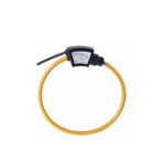
RPS50 is a multiscale Rogowski coil integrator, powered directly from the mains. An integrator is essential to equalize and shift by 90° the output signal from the Rogowski coils. It consists of an active electronic circuit with negligible offset and a good linearity.
RPS50 can be combined with MFC150 coil series. The module is available in the standard configuration with one of the 3 following fullscales: 0.5, 2.5, 10 kA; 2.5, 10, 50 kA; 10, 50, 250 kA (see chapter 9).
On request the input value and the output full scale can be customized according to the application.
RPS50 and a Rogowski current transducer is a very flexible system, suitable for high power load analysis, impulsive current monitoring, DC ripple measurement, etc.
Due to its specific features, flexible Rogowski coil is an extremely comfortable solution for current measurement and can be used in a number of cases where traditional current transducer is not the adequate solution
PRELIMINARY VERIFICATION
![]() NOTE
NOTE
At the opening the box, check that the instrument has not been damaged during transport. If the instrument appears to be damaged, contact the after sale service.
The box contains:
- the instrument
- the user manual
INSTALLATION
![]() NOTE
NOTE
The equipment complies with the 89/366/EEC, 73/23/EEC standards and following amendments. However, if not properly installed, it may generate a magnetic field and radio interference.
The environment in which the instrument is installed must satisfy the following features:
- no vibrations
- indoor area
- temperature between -10°C and +50°C (+14°F and +122°F)
- storage between -25°C and +70°C (-13°F and +158°F)
- max. humidity 80% (no condensation)
![]() NOTE
NOTE
The instrument must not be exposed to sun rays.
Fastening to DIN EN 50022 rail is provided for the instrument.
To mount the instrument on DIN rail, follow the description below:
- Hang up to DIN rail the higher fastening part of the instrument.
- Pull the instrument downward and against the DIN rail. The fastening down side of the instrument will be hang up on the DIN rail.
- To remove the instrument, use a screwdriver, as a lever, on the iron hook on the base of the instrument.

SAFETY MEASURES & ELECTRICAL CONNECTIONS
![]() WARNING!
WARNING!
Electrical instrument connections must be carried out only by qualified technicians aware of the risks involved to the presence of voltage.
![]() WARNING!
WARNING!
Before making any connection, check that the instrument is NOT POWERED and:
- the conductor wires are not powered.
- the power supply corresponds to the values on the instrument label.
- the instrument has been installed in a vibration-free and a suitable temperature environment (see chapter 4).
- the wiring is carried out in accordance with the standards in force in the country where the instrument is to be installed.

![]() NOTE For coil connection, please refer to the following table:
NOTE For coil connection, please refer to the following table:
| COIL CABLES | ||
| with edges | stripped | |
| GND (-) | WHITE edge | BLUE cable |
| IN (+) | YELLOW edge | WHITE cable |
| S | – | shield |
POWER SUPPLY
![]() WARNING! Before connecting the power supply, check if it corresponds to the value on the instrument label (85…250 Vac).
WARNING! Before connecting the power supply, check if it corresponds to the value on the instrument label (85…250 Vac).
The instrument has not a protection fuse on the power supply, therefore the installer must protect it with a current breaker and an overcurrent protection device (315mA delayed fuse, T type).
ANALOG OUTPUTS
Two different outputs are available:
- the standard AC output carrying out the instantaneous value, with 3 Vrms fullscale
- an optional DC output carrying out the RMS value of the measured current. The available values are: 0…20 mA, 4…20 mA, 0…1 V or 0…10 V.
![]() WARNING! Check if the external load parameters comply to the RPS50 Technical Specifications.
WARNING! Check if the external load parameters comply to the RPS50 Technical Specifications.
FULLSCALE SELECTION
The dip-switches allow to select the full scale value. The following table shows possibilities for full scale selection, according to instrument factory preset range.
| RPS50 MODEL | RANGE | SWITCH SELECTION | TRIMMER | ||
| 1 | 2 | 3 | |||
| 0.5 – 2.5 – 10 kA | 0.5 kA | ON | OFF | OFF | A |
| 2.5 kA | OFF | ON | OFF | B | |
| 10 kA | OFF | OFF | ON | C | |
| 2.5 – 10 – 50 kA | 2.5 kA | ON | OFF | OFF | A |
| 10 kA | OFF | ON | OFF | B | |
| 50 kA | OFF | OFF | ON | C | |
| 10 – 50 – 250 kA | 10 kA | ON | OFF | OFF | A |
| 50 kA | OFF | ON | OFF | B | |
| 250 kA | OFF | OFF | ON | C | |
DC OUTPUT RESPONSE TIME SELECTION
![]() WARNING!
WARNING!
The dip-switch 4 allows to select the response time only for DC output (optional). The following table shows the response time selection.
| SWITCH 4 SELECTION | RESPONSE TIME |
| ON | 150 ms |
| OFF | 50 ms |
CALIBRATION
![]() WARNING!
WARNING!
The RPS50 is factory calibrated for best measurement performance. However, it is possible to perform a customized calibration of each measuring scale if needed.
The following picture shows the three calibration trimmers with the relevant fullscale values described in the table (full scale values expressed in kA). Carry out the calibration following the indications relevant to the own instrument fullscale (1, 2 or 3).

| FULLSCALE | ||||
| A | B | C | ||
| RANGE | 1 | 0.5 | 2.5 | 10 |
| 2 | 2.5 | 10 | 50 | |
| 3 | 10 | 50 | 250 | |
TECHNICAL SPECIFICATIONS
| POWER SUPPLY | |||
| Rated Voltage | 80…250 Vac 50/60 Hz | ||
| Consumption | 1.5 VA max | ||
| ELECTRICAL CHARACTERISTICS | |||
| Input | no. 1 for Rogowski coil | ||
| Input level (RMS) (1) | 100 mV / 1 kA @ 50 Hz, other values on request | ||
| Output 1 | 1 Vrms (max crest factor 4.5) | ||
| 3 Vrms (max crest factor 1.5) | |||
| other values on request | |||
| Output 1 permissible load | ›10 kOhm | ||
| Output 2 (optional) | 0…20 mA, 4…20 mA, 0…1 V or 0…10 V on request | ||
| Output 2 DC voltage load | ›100 kOhm | ||
| Output 2 DC current load | £ 300 Ohm | ||
| Available full scales | 1) A: 0.5kA | B: 2.5kA | C: 10kA |
| (on request) | 2) A: 2.5kA | B: 10kA | C: 50kA |
| 3) A: 10kA | B: 50kA | C: 250k | |
| Accuracy (2) | better than ±1% of full scale | ||
| ENVIRONMENTAL CONDITIONS | |||
| Operating temperature | from -10°C to +50°C (from +14°F to +122°F) | ||
| Storage temperature | from -25°C to +70°C (from -13°F to +158°F) | ||
| Relative humidity | 80% max. without condensation | ||
| MECHANICAL CHARACTERISTICS | |||
| Material | plastic enclosure | ||
| Protection degree | IP20 | ||
| Size / Weight | 115 x 100 x 23 mm / approx. 117 gr | ||
| STANDARDS COMPLIANCE | |||
| Safety | 73/23/EEC and 93/68/EEC directives, EN61010.1 safety standard | ||
| EMC | 89/366/EEC directive and following modifications 93/31/EEC and 93/68/EEC, EN50081-2, EN50082-2, EN61326/A1 | ||
(1) The Rogowski coil output is proportional to the rate of change of current. The calculation formula is: AmpereRMS x Hertz x K x 10-6, where K depends on manufacturing. The K value is 2 for 100mV models.
(2) RPS50 is delivered with the specified accuracy. Moreover, the calibration of each scale is adjustable by user to achieve the maximum accuracy in conjunction with the coil.
(3) The low limit is approximate and it is determined by noise effect on very low signals.

Documents / Resources
 |
algodue RPS50 Multiscale Rogowski Coil Adapter [pdf] User Manual RPS50, RPS50 Multiscale Rogowski Coil Adapter, Multiscale Rogowski Coil Adapter, Rogowski Coil Adapter, Coil Adapter, Adapter |