algodue MFC140 Rogowski Coil Current Sensor

INTRODUCTION
The manual is intended only for qualified, professional and skilled technicians, authorised to act in accordance with the safety standards provided for the electrical installations. This person must have appropriate training and wear suitable Personal Protective Equipment.
![]() WARNING! It is strictly forbidden for anyone who does not have the above-mentioned requires to install or use the coil.
WARNING! It is strictly forbidden for anyone who does not have the above-mentioned requires to install or use the coil.
It is forbidden to use the coil for purposes other than intended ones, specified in this manual. The symbols on the product are following described:
![]() Attention! Refer to the user manual.
Attention! Refer to the user manual.
![]() Protected throughout by DOUBLE INSULATION or REINFORCED INSULATION.
Protected throughout by DOUBLE INSULATION or REINFORCED INSULATION.
![]() Do not apply around or remove from HAZARDOUS LIVE conductors without additional protective means.
Do not apply around or remove from HAZARDOUS LIVE conductors without additional protective means.
![]() Complies with the relevant European standards.
Complies with the relevant European standards.
AVAILABLE MODELS
|
MODEL |
Built-in INTEGRATOR | OUTDOOR use |
| MFC140 |
• |
|
|
MFC140/F |
• |
• |
The Rogowski coil must be installed in an environment which are according to the max operation conditions of the coil itself.
![]() WARNING! The connection and installation of the Rogowski coil must be carried out only by qualified technicians aware of the risks involved to the presence of voltage and current. Before carrying out an operation, check if:
WARNING! The connection and installation of the Rogowski coil must be carried out only by qualified technicians aware of the risks involved to the presence of voltage and current. Before carrying out an operation, check if:
- bare conductor wires are not powered, 2. there are no neighbour bare powered conductors
NOTE: The Rogowski coil complies with IEC 61010-1 and IEC 61010- 2-032 standards and following amendments. The installation must be carried out in accordance with the standards in force, the instructions of this user manual and the coil insulation value in order to avoid any danger for people.
The Rogowski coil is a sensor for accurate measurement so it must be handled with care. Before use, read the following instructions carefully
- Do not use the product if damaged.
- Always wear protective clothing and gloves when required.
- Avoid to strongly twist, blow and to perform pulling load on the product, the measurement accuracy may be impaired.
- Do not paint the product.
- Do not put metallic labels or other objects on the product: the insulation may be impaired.
- It is forbidden any use of the product different from the manufacturer specifications.
MOUNTING
![]() WARNING! Before installing the coil round a conductor not insulated, check that it is not powered otherwise switch the circuit OFF.
WARNING! Before installing the coil round a conductor not insulated, check that it is not powered otherwise switch the circuit OFF.
![]() WARNING! Check if the coil is properly installed: a bad locking can affect measurement accuracy and the coil will become sensitive to adjacent conductors or other sources of electromagnetic fields.
WARNING! Check if the coil is properly installed: a bad locking can affect measurement accuracy and the coil will become sensitive to adjacent conductors or other sources of electromagnetic fields.
NOTE: Coil must not fit tightly round the conductor, therefore its internal diameter must exceed that of the conductor.
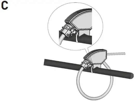
To carry out the installation, proceed as follow:
- Fit the coil round the conductor, bringing the coil ends together.
- Lock the coil by turning the ring until the two hooks will be overlapped (see picture A).
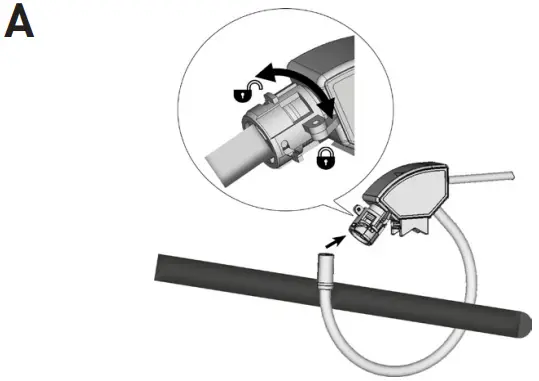
- Seal the locking if requested (see picture B).
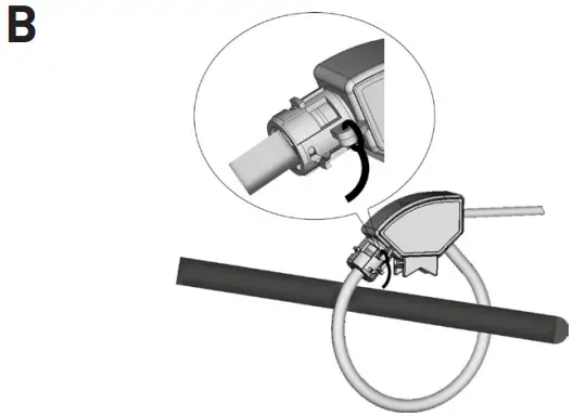
- Fix the coil on the conductor if requested (see picture C).
CONNECTIONS
The coil has an arrow indicating the load side.
In case of model WITHOUT integrator refer to picture D:
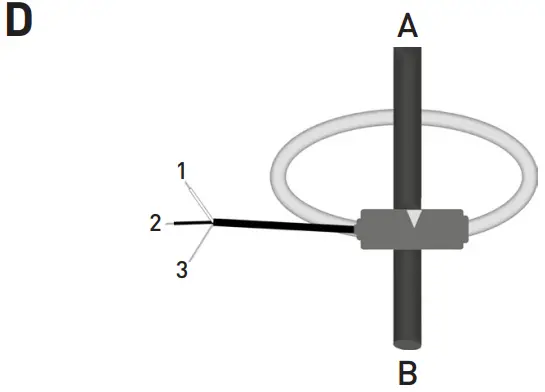
A = SOURCE
B = LOAD
- WHITE wire, OUT+
- BLACK wire, OUT3. SHIELD, connect to GND or OUT- If the cable is provided with crimp pins:
- YELLOW crimp pin, OUT+
- WHITE crimp pin, OUT
In case of model WITH integrator refer to picture E:
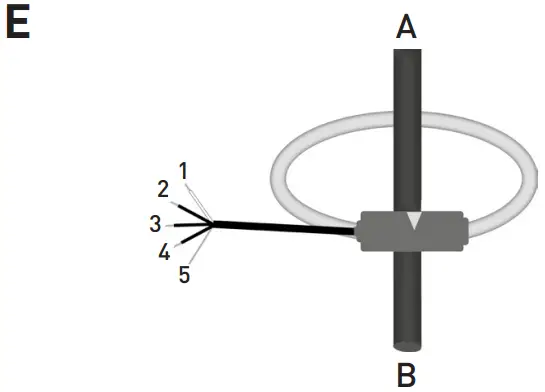
A = SOURCE
B = LOAD
- WHITE wire, OUT+
- BLACK wire, OUT3. RED wire, positive power, 4…26 VDC
- BLUE wire, negative power, GND
- SHIELD, connect to GND
The coil is protected against reverse polarity of the power supply.
MAINTENANCE
Refer to the following instructions carefully for the product maintenance.
- Keep the product clean and free of surface contamination.
- Clean the product with a soft cloth damp with a water and neutral soap. Avoid to use corrosive chemical products, solvents or aggressive detergents.
- Make sure the product is dry before further use.
- Do not use or leave the product in particularly dirty or dusty environments.
TECHNICAL FEATURES
NOTE: For any doubt on the installation procedure or on product application, please contact our technical services or our local distributor
| COIL | |
| Coil length | 150 … 500 mm |
| Sensor internal diameter | 40 … 150 mm |
| Cord diameter | 7.2 ±0.2 mm |
| Jacket material | Polyphenylene and thermoplastic elastomer |
| Fastening | Bayonet holder |
| Weight | 150 … 500 g |
| ELECTRICAL CHARACTERISTICS FOR MODEL WITHOUT INTEGRATOR | |
| Nominal output rate | 100 mV / kA @ 50 Hz (RMS values) Refer to the value indicated on the product label |
| Max measurable current | 600 A with 150 … 280 mm coil length 2500 A with 290 … 410 mm coil length 5000 A with 420 … 500 mm coil length |
| Coil resistance | 170 … 690 Ω |
| Positioning error | Better than ±1% of reading |
| Frequency | 50/60 Hz |
| Overvoltage category | 1000 V CAT III, 600 V CAT IV |
| Pollution degree | 3 |
| Insulation test voltage | 7400 VRMS / 5 s |
| ELECTRICAL CHARACTERISTICS FOR MODEL WITH INTEGRATOR | |
| Power voltage | 4 … 26 VDC |
| Max consumption | 5 mADC |
| Nominal output rate | 333 mV / FS (RMS values) FS changes according to the model: 200, 250, 600, 1000 A Refer to the value indicated on the product label |
| Positioning error | Better than ±1% of reading |
| Frequency | 50/60 Hz |
| Overvoltage category | 1000 V CAT III, 600 V CAT IV |
| Pollution degree | 3 |
| Insulation test voltage | 7400 VRMS / 5 s |
| CONNECTION CABLE FOR MODEL WITHOUT INTEGRATOR | |
| Type | 3 x 24 AWG shielded |
| Length | 3 m. Other lengths on request: 5, 7, 10, 15 m |
| CONNECTION CABLE FOR MODEL WITH INTEGRATOR | |
| Type | 5 x 24 AWG shielded |
| Length | 3 m. Other lengths on request: 5, 7, 10, 15 m |
| ENVIRONMENTAL CONDITIONS | |
| Protection degree | IP68 |
| Altitude | Up to 2000 m over sea-level |
| Operating temperature | -40 … +75°C up to 2500 A with 150 … 410 mm coil length -40 … +60°C up to 5000 A with 420 … 500 mm coil length |
| Storage temperature | -40 … +90°C |
| Relative humidity | 0 … 95% |
| Installation and use | Outdoor |
| STANDARD COMPLIANCE | |
| IEC standards | IEC 61010-1, IEC 61010-2-032, IEC 60529 |
Customer Support
Algodue Elettronica Srl
Via P. Gobetti, 16/F • 28014 Maggiora (NO), ITALY
Tel. +39 0322 89864 • +39 0322 89307
www.algodue.com • support@algodue.it

Documents / Resources
 |
algodue MFC140 Rogowski Coil Current Sensor [pdf] User Manual MFC140, MFC140-F, MFC140 Rogowski Coil Current Sensor, Rogowski Coil Current Sensor, Coil Current Sensor, Current Sensor, Sensor |


