
1. Overview
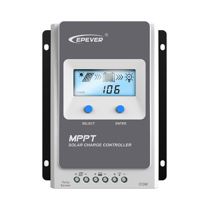
The EPEVER Tracer-AN G3 MPPT Solar Controller represents the latest advancement in solar management technology, offering significant improvements over previous generations. This cutting-edge solar power controller is engineered to maximize energy harvest through its advanced Maximum Power Point Tracking (MPPT) technology, intelligently adapting to diverse solar conditions. It supports a wide array of battery types, including lithium batteries, and integrates robust safety features such as overcharge protection and automatic system voltage recognition, ensuring broad compatibility and enhanced safety across various solar power setups.
Key enhancements in the G3 series include expanded communication capabilities, facilitating seamless integration with monitoring devices and software. This provides users with comprehensive control and visibility over their solar energy systems. With its durable construction and intuitive interface, the Tracer-AN G3 empowers both new users and seasoned professionals to efficiently optimize their solar installations. Whether for residential sustainability or large-scale solar operations, the Tracer-AN G3 delivers high efficiency and smart technology.
2. Product Features
- Constant Voltage Output Function: Enables direct load supply from the controller's battery terminal without batteries or battery protection cutoff, expanding system applications and ensuring stability.
- Advanced MPPT Technology: Achieves maximum tracking efficiency higher than 99.5%.
- High Conversion Efficiency: Maximum DC/DC conversion efficiency of 98%.
- Multi-Battery Type Support: Compatible with various battery types, including lithium batteries.
- Battery Temperature Compensation: Features stable self-activation function for optimal charging.
- LCD Screen: For easy battery parameter setting and system monitoring.
- Comprehensive Electronic Protection: Built-in safeguards against various electrical faults.
- Low Self-Consumption: Operates with self-consumption lower than 10mA.
- Multiple Load Work Modes: Offers 6 distinct load working modes for diverse applications.
- Flexible Parameter Setting: Parameters can be set via PC software, mobile APP, or remote meter.
- RS485 Communication Interface: Supports optional 4G or Wi-Fi modules for enhanced connectivity.
- No-Battery Working Mode: Supports operation without a connected battery.
- Ultra-quiet & Low Power Design: Enhanced energy savings (<8mA/12V, <5mA/24V) and quiet operation.

3. Setup and Installation
3.1 Connection Order
It is crucial to follow the correct connection and disconnection sequence to prevent damage to the controller and other system components. Always connect the solar system in the following order:
- Connect the battery.
- Connect the load.
- Connect the PV array (solar panels).
To disconnect the solar system, reverse the order:
- Disconnect the PV array.
- Disconnect the load.
- Disconnect the battery.

3.2 Important Warnings
- The battery must be connected first. Never connect the solar panel array to the controller without or before connecting the battery.
- DO NOT connect any inverter, wind generator, alternator, or charger directly into the charge controller. These devices should be connected with the battery and an appropriate fuse.
- For long distances between the PV array and the controller, or between the controller and the battery, use larger gauge wires to minimize voltage drop and optimize performance. Refer to local electrical codes and wire sizing charts for appropriate wire selection.
3.3 Constant Voltage Output Configuration
The TracerANG3 supports a Constant Voltage Output function. This allows the controller's battery terminal to directly supply the load even without a connected battery or if battery protection cutoff is active. This feature expands system application possibilities and ensures maximum system stability during continuous operation, offering comprehensive compatibility with various lithium batteries.

4. Operating Modes
The TracerANG3 offers 6 distinct load working modes to cater to various application scenarios:
- Manual Mode: Load is controlled manually by the user.
- Light ON/OFF Mode: Load turns on automatically at dusk and off at dawn.
- Light ON/OFF + Timer Mode 1: Load turns on at night and off during the day, with a set timer for the ON duration.
- Light ON/OFF + Timer Mode 2: Load turns on during the day and off at night, with a set timer for the ON duration.
- Real-time Control Mode: Load operation is controlled based on real-time settings and schedules.
- Always ON Mode: Load remains continuously powered.

5. Specifications
| Attribute | Value |
|---|---|
| Brand Name | EPEVER (EVSOLAR) |
| Model Number | TracerANG3 |
| Current Ratings Available | 10A, 20A, 30A, 40A |
| System Voltage | 12V/24V Auto Recognition |
| Application | Charger Controller, Solar System Controller, Solar Working Station |
| Is Smart Device | Yes |
| Customization | Yes |
| Origin | Mainland China |
| Certification | CE |
| MPPT Tracking Efficiency | >99.5% |
| DC/DC Conversion Efficiency | Max. 98% |
| Self-Consumption | <10mA |
| Energy Savings (Standby) | <8mA/12V, <5mA/24V |
6. Maintenance
To ensure optimal performance and longevity of your EPEVER TracerANG3 MPPT Solar Charge Controller, regular maintenance is recommended:
- Visual Inspection: Periodically check the controller and all connections for any signs of damage, corrosion, or loose wiring. Ensure all terminals are securely fastened.
- Cleanliness: Keep the controller clean and free from dust, dirt, and debris. Use a dry, soft cloth for cleaning. Do not use abrasive cleaners or solvents.
- Ventilation: Ensure that the controller's ventilation openings are not obstructed to allow for proper heat dissipation.
- Battery Health: Monitor your battery's health and charge levels regularly. Ensure the battery type settings in the controller match your installed battery.
- Firmware Updates: Check the manufacturer's website periodically for any available firmware updates that may improve performance or add new features.
- Environmental Conditions: Ensure the controller is installed in a dry, well-ventilated area, protected from direct sunlight, extreme temperatures, and moisture.
7. Troubleshooting
- Controller Not Powering On: Check battery connections and ensure the battery voltage is within the controller's operating range. Verify fuses are intact.
- No Charging from PV: Ensure solar panels are connected correctly and receiving sufficient sunlight. Check PV array voltage and current. Verify that the PV input voltage does not exceed the controller's maximum input voltage.
- Load Not Working: Check load connections and ensure the load current does not exceed the controller's rated load current. Verify the selected load working mode (e.g., Manual Mode, Always ON Mode).
- Unable to Change Charging Parameters (e.g., charging times): If you are experiencing difficulty changing charging parameters via the LCD screen, ensure you are in the correct menu and have the necessary access rights. For advanced settings or if the LCD interface is limited, consider using one of the external programming methods: Remote Meter (MT52), PC Software (requires RS485 cable: CC-USB-RS485-150U), or Phone APP (requires WIFI or BLE module). These external tools often provide more comprehensive control and diagnostic capabilities.
- Overcharge/Over-discharge Protection: The controller has built-in protections. If these activate, check battery voltage, load consumption, and charging parameters. Ensure battery type settings are correct.
8. User Tips
- For optimal performance with lithium batteries, it is highly recommended to use the PC software or mobile app for precise parameter configuration. This allows for fine-tuning charge voltages and other settings specific to your lithium battery's Battery Management System (BMS) requirements.
- When setting up load working modes, especially timer-based ones, double-check the local time settings if the controller has a real-time clock function, or ensure your external communication device (PC/APP) is synchronized.
- Always ensure proper wire sizing for all connections (PV, battery, load) to minimize energy loss and prevent overheating, especially for higher current models (30A, 40A).
9. Warranty and Support
For warranty information, technical support, or service inquiries, please refer to the official EPEVER website or contact your authorized dealer. Keep your purchase receipt and product serial number handy when seeking support.