1. Introduction
The GODIAG GT100 is an advanced ECU connector and protocol communication testing tool designed for automotive diagnostics, programming, and coding. It facilitates connecting to ECU modules for various operations and helps verify the communication signals of diagnostic and programming tools.
Key Features:
- Serves as a testing platform for OBDII protocol communication detection.
- Supports ECU maintenance, diagnosis, programming, and coding.
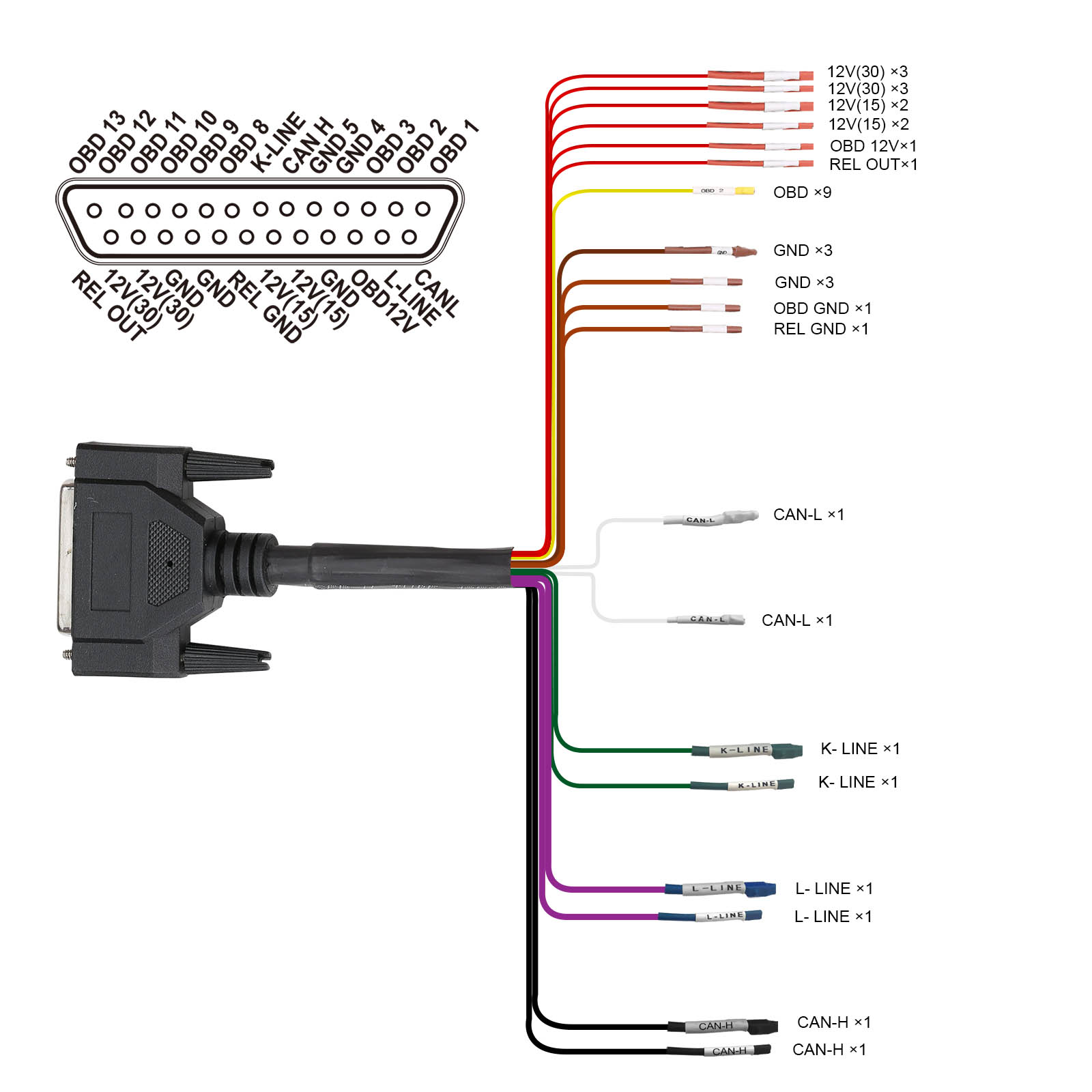
- Converts car OBD2 interface into a 6-pin interface for signal detection and electrical level conversion.
- Enables connection to single or multiple vehicle modules.
- Assesses the communication status between the car and diagnostic tools.
- Provides power to the vehicle during battery replacement to prevent data loss or module locking.
- Compatible with various diagnostic devices such as Xhorse VVDI2, Autel, Launch, and Foxwell.
2. Setup and Connections
2.1 Hardware Connection Diagram
Refer to the diagram below for a comprehensive overview of the GODIAG GT100 hardware connections.
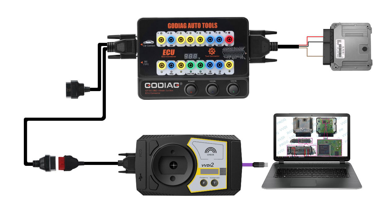
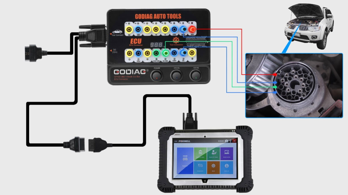
2.2 ECU Connection (Single Module)
The GT100 allows for convenient single-module diagnosis and programming.
- Connect the ECU to the GT100 using the provided colored jumper cables. If the ECU uses a CAN protocol, ensure to connect a 120 ohm resistor if required by the specific ECU.
- Power the Godiag GT100 either by connecting it to the car's OBDII diagnostic interface or by using an AC power adapter.
- Connect your diagnostic tool or ECU programmer to the GT100 to perform diagnosis and programming on the single ECU.
2.3 Powering the GT100
- Plug the power adapter into the GT100.
- Turn on the power switch of the GT100.
- Then, turn on the ECU power switch.
- Finally, activate the ignition switch (if applicable for the specific setup).
3. Operating Instructions
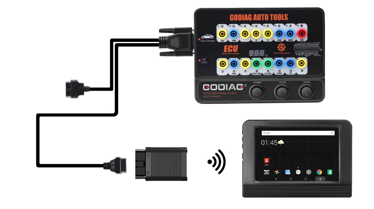
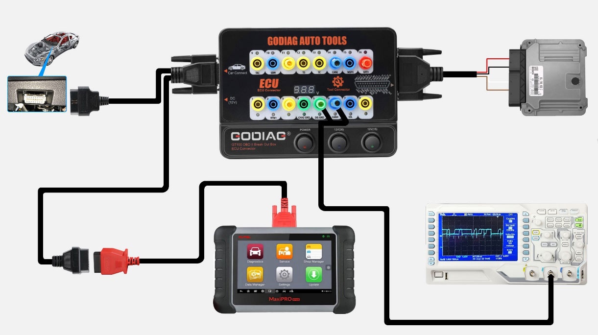
3.1 OBDII Protocol Detection and Communication Monitoring
The GT100 helps verify the communication status between your vehicle and diagnostic tool.
- Connect the GODIAG GT100 to the OBDII diagnostic port of your vehicle.
- Once the device displays the voltage, turn on the power switch of the GODIAG GT100.
- Connect your diagnostic tool to the GT100. As the tool communicates with the car, the LED indicator for the corresponding protocol will light up or flash. For CAN protocol, it will show maximum brightness, then dim or twinkle weakly upon successful communication.
- Monitor the voltage displayed on the GT100. If the voltage drops below 11V, it is recommended to stop diagnosis and programming to prevent potential issues like vehicle startup failure, data loss, or module locking.
OBDII Pinout Indicator Meaning:
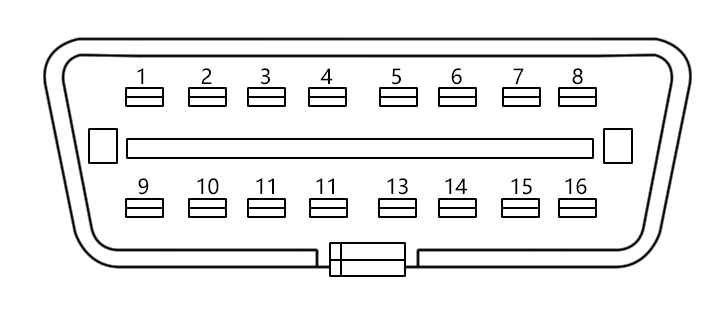
| Pin Number | Function |
|---|---|
| 1 | Manufacturer custom |
| 2 | SJE1850 wire |
| 3 | Manufacturer custom |
| 4 | Power grounding |
| 5 | Signal grounding |
| 6 | SAEJ2284 CAN high |
| 7 | ISO9141-2 & ISO/DIS 4230-4K wire |
| 8 | Manufacturer custom |
| 9 | Manufacturer custom |
| 10 | SJE1850 wire (bus-) |
| 11 | Manufacturer custom |
| 12 | Manufacturer custom |
| 13 | Manufacturer custom |
| 14 | SAEJ2284 CAN low |
| 15 | ISO9141-2 & ISO/DIS 4230-4L wire |
| 16 | Car battery positive |
3.2 Using Banana Plug Extension
The banana plug extension allows you to extend the car's OBDII 16-pin interface for easier access and to test the voltage waveform of the OBDII interface.
3.3 Converting OBD1 to Standard OBD2
The GT100 can convert an OBD1 diagnostic interface to a standard OBD2 interface, following the specific diagnostic protocol.
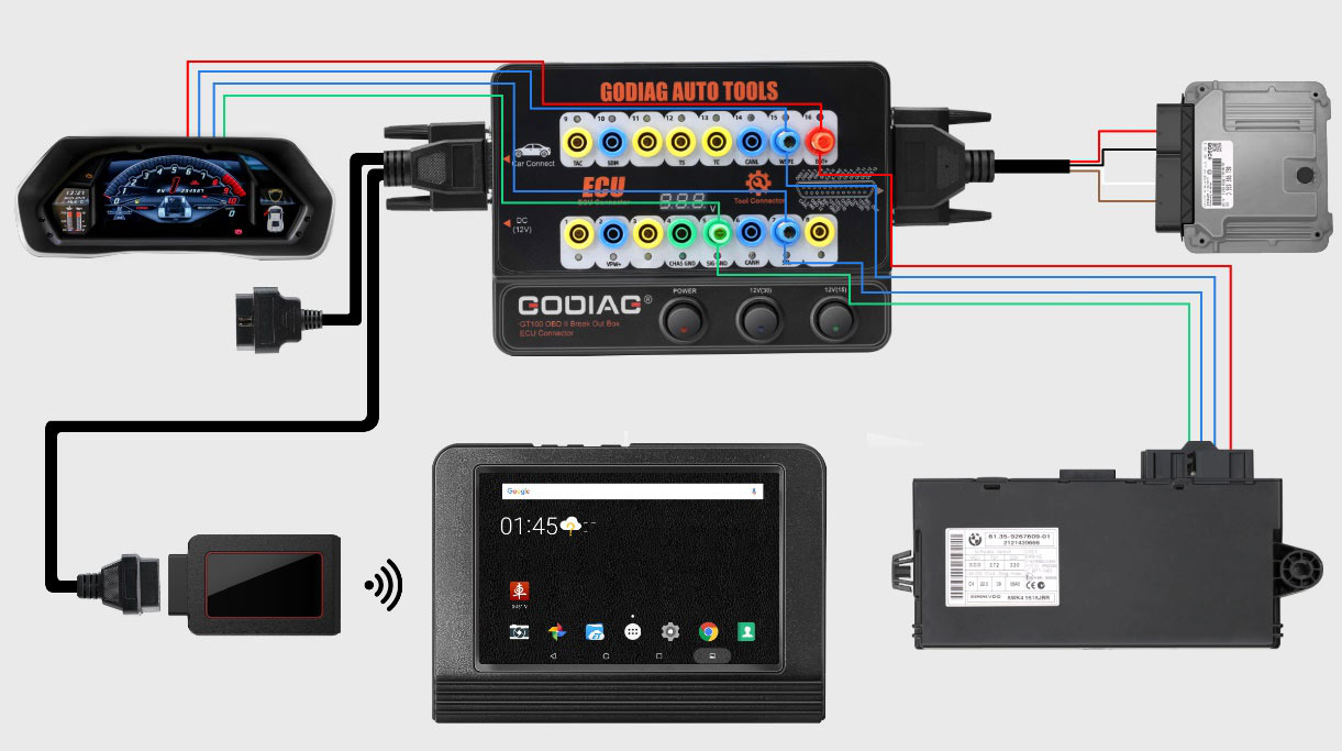
3.4 Connecting Multiple ECU Control Modules
For professional engineers, the GT100 facilitates connecting and working with multiple ECU control modules simultaneously for detection and maintenance.
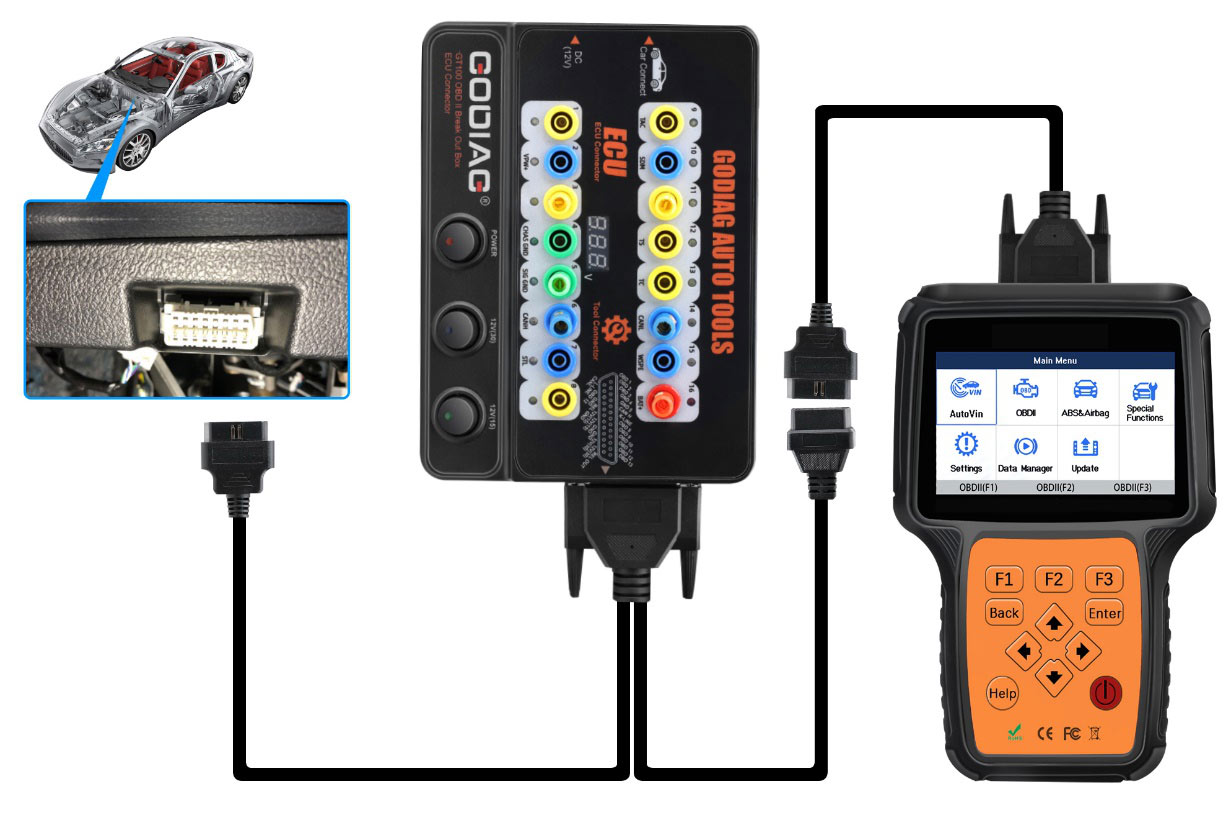
3.5 Using Extension Cables
If the vehicle's diagnostic interface is in a hard-to-reach location or if your diagnostic cable is not long enough, the provided extension cables can extend the connection by 1.2 meters.
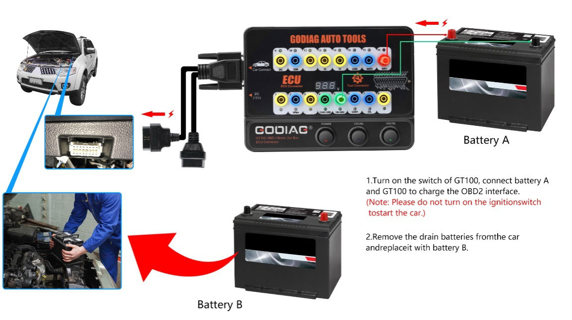
3.6 Powering the Car During Battery Replacement
To prevent data loss, automatic locking, or fault lights when replacing a car battery, the GT100 can maintain power to the vehicle's control modules.
- Connect an external battery (Battery A) to the GODIAG GT100 using pins 16 (Car battery positive), 4 (Power grounding), and 5 (Signal grounding). Then connect the GT100 to the car's OBD2 diagnostic interface.
- Turn on the power switch of the GODIAG GT100.
- Important: Do not turn on the ignition switch or start the car during this process.
- Proceed to replace the vehicle's old battery with a new one (Battery B). This ensures continuous power to the vehicle's control modules, preventing data loss or malfunctions.
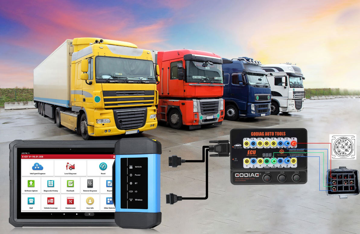
3.7 Truck OBD1 to OBD2 Conversion
The GT100 can convert the OBD1 port of special trucks to a standard OBD2 diagnostic port, adhering to the specific protocol.
3.8 Diagnostic Process Demonstration (Video)
This video demonstrates how to use the GODIAG GT100 with a ThinkCar Pro device to read Diagnostic Trouble Codes (DTCs) from a Bosch ECU.
4. Specifications
| Item | Specification |
|---|---|
| Diagnostic port | OBDII |
| Working voltage | DC 9V-24V |
| Work and power | 0.5-0.6W |
| Adapter power | Input AC100V-240V, Output DC12V 1A |
| Operating temperature range | -20 to 70 °C (-4 to 158 °F) |
| Storage temperature range | -40 to 85 °C (-40 to 185 °F) |
| Dimension | L: 23cm, W:18cm, H:7cm |
5. Troubleshooting
- No Communication with Vehicle/ECU:
- Check all cable connections to ensure they are secure and correctly plugged into the GT100, ECU, and diagnostic tool.
- Verify the power supply to the GT100 and ensure the power switches are turned on.
- Observe the LED indicators on the GT100. If no protocol LED lights up or flashes, there might be an issue with the vehicle's OBDII port or the ECU wiring.
- Ensure the vehicle's battery voltage is above 11V. Low voltage can prevent proper communication.
- Auto VIN Identification Failed:
- If the diagnostic application fails to automatically identify the Vehicle Identification Number (VIN), manually select your car model and year within the application.
- Diagnostic Tool Not Connecting via Bluetooth:
- Ensure Bluetooth is enabled on your diagnostic device (e.g., smartphone, tablet).
- Verify that the GT100's Bluetooth indicator is active.
- Try restarting both the GT100 and your diagnostic device.
6. User Tips
- Maintain Stable Power: Always monitor the voltage displayed on the GT100, especially during critical operations like ECU programming. A stable power supply is crucial to prevent interruptions and potential damage to vehicle modules.
- Organize Jumper Cables: When connecting to ECUs, use the colored jumper cables systematically and double-check your connections against wiring diagrams to avoid errors.
- Utilize Extension Cables: For vehicles with hard-to-reach OBDII ports, the extension cables are invaluable for comfortable and secure connections.
- Manual VIN Entry: If automatic VIN detection fails in your diagnostic software, be prepared to manually enter the vehicle details to proceed with diagnostics.
7. Maintenance
- Cleaning: Keep the GT100 unit and all cables clean and free from dust, dirt, and moisture. Use a soft, dry cloth for cleaning.
- Storage: Store the device and its accessories in a dry, cool place, away from direct sunlight and extreme temperatures.
- Cable Care: Avoid bending or crimping the cables excessively. Inspect cables regularly for any signs of wear or damage. Replace damaged cables immediately to ensure safe and reliable operation.
- Software Updates: Regularly check for software updates for your diagnostic tools and applications that interface with the GT100 to ensure compatibility and access to the latest features and vehicle coverage.
8. Warranty and Support
The GODIAG GT100 comes with a one-year warranty from the date of purchase. For technical support, troubleshooting assistance, or warranty claims, please contact the manufacturer or your authorized dealer. Ensure to provide your purchase details and a clear description of the issue for efficient service.
9. Package Contents
The GODIAG GT100 package includes the following items:
- 1 x GODIAG GT100 Host Unit
- 1 x OBD 2-in-1 Extension Cable
- 1 x Colored Jumper Cable Set
- 1 x 12V Power Supply Adapter
- 1 x 120 Ohm Resistance
- 6 x Banana Plugs
- 24 x Wire Accessories (Dupont 2.54mm connector female pins)


