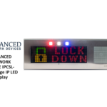
ADVANCED IPCDS-RWB-U Double Sided IP Display

Specifications
- Product: Double-Sided IP Display with Universal Mount
- Model: IPCDS-RWB-U
- Mounting Options: Wall Mount, Ceiling Mount
- Network Cable Compatibility: CAT5 or CAT6 Ethernet cable
- Power Input: PoE (Power over Ethernet)
Installation Instructions
Wall Mount Installation
- Pull ethernet cable from the wall through the bracket arm.
- Attach bracket arm to wall using appropriate mounting hardware.
- Note keyhole orientation with narrow channel at the bottom.
Ceiling Mount Installation
- Detach network cable coupler from internal network cable and insert disconnected cable into the device.
- Run network cable (CAT5 or better) from POE+ switch or injector through bracket arm.
- Attach bracket arm to load-bearing ceiling supports using appropriate mounting hardware.
- Remove hex head bolts securing the mounting bracket to the main enclosure.
- Remove screws and small cover plate to expose opening on top of the device.
- Relocate hex head bolts to the top thread holes, leaving threads exposed for bracket arm clearance.
- Remove mounting screws and display face carefully without disconnecting internal cables.
- Reattach stainless-steel baffle and secure with side screws.
- Connect network coupler on the device to the network cable from the ceiling-mounted bracket arm.
Device Operation
- Connect the network cable to a PoE network switch or injector with a DHCP server.
- The unit should boot up and display the time within 30 seconds.
- Refer to the IPClockWise User Manual or third-party software guide for further instructions.
FAQ
Q: How do I know if the unit is properly installed?
A: The unit should boot up and display the time within 30 seconds of connecting to a PoE network switch or injector.
Double-Sided IP Display with Universal Mount
(IPCDS-RWB-U) Installation
INSTALLATION INSTRUCTIONS
The Double-Sided IP Display ships with ferrite, and comes configured for wall mount installation. If concerned with line performance, wrap CAT5 or CAT6 Ethernet cable around ferrite once and clamp shut.
WARNING: REMOVE POWER FROM DEVICE WHEN MAKING ANY INTERNAL CABLE CHANGES DURING INSTALLATION
Wall Mount Installation
- Loosen hex head bolts by ½” to allow bracket arm to clear safety studs. Tuck the ethernet cable into the device, leaving the ethernet coupler attached as shown. Separate bracket arm from main assembly. Use included template or bracket arm itself for marking wall mounting locations.

- Pull ethernet cable from the wall through the bracket arm. Attach bracket arm to wall using mounting hardware appropriate to the facility building materials. Note keyhole orientation with narrow channel of keyhole at bottom.

- Connect the ethernet cable from the wall (previously routed through the bracket) to the coupler sticking out of the device. Align hex head bolts with keyhole feature in bracket arm and slide through large opening of keyhole. Allow device to drop into narrow channel of keyhole as safety studs enter top of keyhole. Bracket arm should support weight of product while tightening hex head bolts. Be sure no cables are pinched or trapped during the above process. Verify parts sit flush to each other and safety studs clear the bracket arm.

Ceiling Mount Installation
- Detach network cable coupler from internal network cable, and stuff the disconnected network cable into the device.

- Remove the two hex head bolts securing the mounting bracket to the main enclosure, and remove bracket. Use included template or bracket arm itself for marking ceiling mounting locations.

- Run network cable (CAT5 or better) from POE+ switch or injector through bracket arm in direction shown, then attach bracket arm to load bearing ceiling supports using mounting hardware appropriate to the facility building materials. Note orientation of bracket arm to align viewing direction of clock in hallway or room.

- Remove the two screws and small cover plate, exposing the opening on the top of the device. Place the small cover plate over the opening on the side of the device, and fasten it with the two screws.

- Relocate the two hex head bolts removed in step 2 to the top thread holes. Leave 5/8” of threads exposed to allow bracket arm to clear safety studs during installation.
- Remove the four mounting screws and display face as shown. Take care to not disconnect any cables internal to the device during this process.
- Route network cable through the top of device. Reattach the network cable coupler.

- Reversing step 6, reattach the stainless-steel baffle being careful to avoid pinching any wires. Secure with four side screws removed in step 6.
- Connect network coupler on the device to the network cable from the ceiling mounted bracket arm.
- Align hex head bolts with keyhole feature in bracket arm and slide through large opening of keyhole. Slide product laterally to position bolt in narrow channel of keyhole. Safety studs should now be aligned in large portion of keyhole. Bracket arm should support weight of product while tightening hex head bolts. If parts are oriented correctly, safety studs will clear bracket into the large portion of keyhole. Be sure no cables are pinched or trapped during the above process. Verify parts sit flush to each other and safety studs clear the bracket arm.

DEVICE OPERATION
- Connect the other end of the network cable to a PoE (Power over Ethernet) network switch, or a PoE injector, on a network with a DHCP server. Find some supported equipment options listed at https://www.anetd.com/project-resources/prepare-for-installation/
- If properly installed, the unit should boot up and show the time within 30 seconds. See boot sequence below.
- Consult the IPClockWise User Manual ( see https://www.anetd.com/portal/ ) or third-party software guide for further instructions on sending audio and text to the device.
BOOT SEQUENCE
When first powered on, if properly installed, the device should boot, and then display the time as follows:
| 1 |  |
The first screen you will see after powering on the device. For devices with MAC address 20:46:F9:09:xx:xx or lower, the AND jingle should playback over the speakers. |
| 2 |  |
Indicates the current firmware equipped with the device. |
| 3 |  |
Indicates the network MAC address of the device (configured at the factory). |
|
4 |
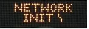 |
Indicates that the device is looking for a DHCP server, among other things. If the boot process hangs in this state, check for a possible network problem (cable, switch, ISP, DHCP, etc.) |
| 5 |  |
Indicates the IP address of the device. DHCP assigns this network-specific address. Otherwise, the static address will appear if configured as such. An audio beep (MAC address 20:46:F9:09:xx:xx or lower) or the AND jingle (MAC address 20:46:F9:0B:xx:xx or higher) should playback over the speakers during this stage. |
| 6 |  |
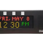
Once all initialization completes, the time will display. If just a colon displays, it cannot find the time. Check the NTP server settings, and check that the Internet connection is working. |
ADDITIONAL RESOURCES
- User Support: https://www.anetd.com/user-support/
- Technical Resources: https://www.anetd.com/user-support/technical-resources/
- AND Limited Warranty: https://www.anetd.com/warranty/
- AND Legal Disclaimer: https://www.anetd.com/legal/
Due to continual product development, specifications and characteristics are subject to change without notice
Advanced Network Devices • 3820 Ventura Dr. Arlington Hts. IL 60004
tech@anetd.com • 847-463-2237 • www.anetd.com
Version 1.1.1 • 11/9/2023
Documents / Resources
 |
ADVANCED IPCDS-RWB-U Double Sided IP Display [pdf] Instruction Manual IPCDS-RWB-U Double Sided IP Display, IPCDS-RWB-U, Double Sided IP Display, Sided IP Display, IP Display, Display |