
POWERING AND SETUP


SMART CONTROLLER (x1) SENSOR PROBE (x1)


CONTROLLER PLATE BOLTS (x2) HEX NUTS (X3)


WOOD SCREWS (WALL HANG) (X2) WIRE TIE (X1)
STEP 1
Plug the sensor probe into the controller’s 3.mm jack. Set the probe near your plants in your grow tent for the most accurate reading.

STEP 2
Plug your device’s UIS connector into one of the controller’s ports to connect and power the controller.

STEP 3
Plug your UIS device’s power cord into an AC power outlet to power it.

You may use the included tie mounts and wire ties to manage the cords.
 OVERVIEW

a. CURRENT TIME
b. CURRENT LEVEL
c. COUNTDOWN
d. PROBE HUMIDITY
e. USER SETTING
f. ALERT ICONS
g. PROBE VPD
h. PROBE TEMP.
i. MODE
j. PORTS
1. Port Button – Cycles through all connected devices.
2. Mode Button – Cycles through the controller’s programming modes.
3. Setting Button – Cycles through the controller settings.
4. Up/Down Buttons – Adjusts the parameters of the mode or setting you are in.
ENVIRONMENTAL GUIDE
Use either VPD or Temp/RH as a guide when programming your devices.
| Plant Stage | VPD | Temperature | Relative Humidity | Light Duration |
| Germination | 0.2-0.8 kPa | 70°-80°F (21°-27°C) | 70%-80% | 13+ Hours/Day |
| Seedling | 0.6-1.1 kPa | 70°-80°F (21°-27°C) | 60%-70% | 13+ Hours/Day |
| Vegetative | 0.6-1.4 kPa | 70°-80°F (21°-27°C) | 50%-70% | 13+ Hours/Day |
| Flowering | 0.8-1.8 kPa | 70°-80°F (21°-27°C) | 40%-60% | 12 Hours/Day |
Use the following steps to select the ideal programming for your device. Each port can run only one mode. Each mode’s functionality can be affected by certain controller settings.

- Select a PORT
ALL 
1 2 3 4 - Select a MODE program for the port to run
OFF Mode / Min Level (pg. 4) ON Mode / Max Level (pg. 4) AUTO Mode (pg. 4) VPD Mode (pg. 5) TIMER TO ON Mode (pg. 5) TIMER TO OFF Mode (pg. 5) CYCLE Mode (pg. 6) SCHEDULE Mode (pg. 6) - Review PROGRAMMING that may affect modes
Max/Min Level Setting (pg.4)
Affects ALL Modes - Review SETTINGS that may affect modes
Transition Setting (pg.8)
Affects AUTO and VPD ModesBuffer Setting (pg.9)
Affects AUTO and VPD Modes - Return to resume programming
 MODES
MODES
OFF MODE (MIN LEVEL) / ON MODE (MAX LEVEL)
OFF MODE
SET TO
3
MIN LEVEL
Sets the minimum level your device will run at in all other modes.
LEVELS 
ON MODE
SET TO
6
MAX LEVEL
Sets the maximum level your device will run at in all other modes.
LEVELS 
AUTO MODE
All four triggers can activate and run simultaneously. Turn off any triggers not in use by holding down the up and down buttons together.
HIGH TEMP. TRIGGER FOR COOLING FANS
Activates your device if temperature levels meet or exceed your set figure.
HIGH TEMP. TRIGGER
HIGH HUMID. TRIGGER FOR DEHUMIDIFIERS
Activates your device if relative humidity levels meet or exceed your set figure.
HIGH HUMID. TRIGGER
LOW TEMP. TRIGGER FOR HEATERS
Activates your device if temperature levels meet or fall below your set figure.
LOW TEMP. TRIGGER
LOW HUMID. TRIGGER FOR HUMIDIFIERS
Activates your device if relative humidity levels meet or fall below your set figure.
LOW HUMID. TRIGGER
VPD MODE
Measures the ambient temperature, relative humidity, and your plant’s leaf temperature. Monitoring this will help you create the ideal evaporation rate for your plant to ensure a steady flow of nutrients from its roots to the rest of its anatomy. VPD Mode is specifically designed for grow applications.

HIGH VPD TRIGGER
Activates your device if VPD levels meet or exceed your set figure.
HIGH VPD TRIGGER
LOW VPD TRIGGER
Activates your device if VPD levels meet or fall below your set figure.
LOW VPD TRIGGER
TIMER TO ON MODE
Sets a timer that will turn on your device at the end of the countdown. This mode will not repeat automatically but must be reset.
TIMER TO OFF
(Countdown End Point)
TIMER TO OFF MODE
Sets a timer that will turn off your device at the end of the countdown. This mode will not repeat automatically but must be reset.
TIMER TO ON
(Countdown End Point)
CYCLE MODE
Sets an ON duration and an OFF duration for your device to cycle through continuously. Both ON and OFF countdown timers must be set in order for your device to properly cycle.
In this example, the ON duration is set to 30 minutes and the OFF duration is set to 1 hour.
Your device will turn on for 30 minutes and turn off for 1 hour. It will then turn on for 30 minutes again before turning off for 1 hour. This cycle will continue until you leave this mode.

SCHEDULE MODE
Sets a daily schedule for your device to trigger on and off. Both ON and OFF clock times must be set in order for your device to be properly scheduled. The controller clock time must also be set under Settings in order for your device to properly follow schedules.
In this example, the ON time is set to 9 AM and the OFF time is set to 7 PM. This will trigger your device to run between 9 AM to 7 PM on a daily basis while you remain in this mode.

 SETTING
DISPLAY SETTING
Adjusts display brightness and auto-dimming. Cycle through levels 1, 2, 3, A2 and A3. A2 and AS set the brightness level at 2 and 3, respectively, dimming to level 1 after 15 seconds of inactivity.

°F/°C SETTING
Changes the displayed units to Fahrenheit or Celsius. All displayed units automatically convert when adjusting this setting.
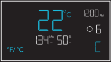
CLOCK SETTING
Adjusts the current clock time. Cycling through 12:00 will automatically change the units to AM or PM.

CALIBRATION SETTING
Adjusts the temp. and humidity readings the sensor probe is measuring. The calibration cycle ranges from -20°F to 20°F (-10°C to 10°C) for temp. and -10% to 10% for humidity.

VPD LEAF OFFSET
Adjusts the sensor probe’s VPD reading in 1° increments. The calibration cycle ranges from -20°F to 20°F (or -10°C to 10°C).

Screen elements are enlarged for display purposes only.
TRANSITION SETTINGS
The transition setting adjusts how your device will shift between levels when triggered to run in AUTO Mode (temperature and/or humidity) or VPD Mode. In high triggers, this will create intervals above your set trigger point. In low triggers, this will create intervals below your set trigger point.
For each interval the probe reading passes, your device’s level will adjust by one. Please note your device’s levels will be limited by your min and max level settings.

BUFFER SETTINGS
This setting creates a gap from your AUTO Mode temperature, humidity, and VPD triggers. This sets a separate trigger-off point to keep your device from triggering too quickly due to small climate fluctuations.
While a buffer setting is active, your device will stay on after triggering, remaining on even after the reading falls below your set trigger point. Your device will only turn off when the reading falls below the separate trigger-off point.
HIGH TRIGGEW
In this example, your set trigger point is 89°F and buffer setting is 6°F. After turning on, your device will stay on until the temperature reaches 83°F.

- Trigger OFF point 83°F
- Trigger ON point 89°F
LOW TRIGGERS
In this example, your set trigger point is 51 °F and buffer setting is 6°F. After turning on, your device will stay on until the temperature reaches 57°F.

- Trigger ON point 51°F
- Trigger OFF point 57°F
 CONTROLLER SHORTCUTS
FACTORY RESE
Hold the mode, up, and down buttons together for 5 seconds to reset your controller and restore factory settings.
HOLD


CONTROLLER LOCK
Hold the setting button to lock your controller in its current mode. Hold the setting button to unlock your controller.
HOLD

HIDE SCREEN
Lock your controller so no settings can be adjusted. See above. Then press the setting button to turn the display off. Pressing it again will turn the display back on.
PRESS
JUMP TO OFF MODE
Hold the mode button for 3 seconds in any mode or setting to automatically jump to OFF Mode.
HOLD
RESE ‘TO OFF/DEFALP
Hold the up and down buttons together for 2 seconds to reset the value of your current mode or controller setting.
HOLD
AUTO INCREASING OR DECREASING
Hold the up or down button to increase or decrease the user setting automatically until you release them.
HOLD HOLD
OR
MORE INFORMATION

Visit our website at www.acinfinity.com for more information on how to program CONTROLLER 69 PRO.
FAQ

WEBSITE | www.acinfinity.com
EMAIL | support@acinfinity.com
PHONE | 626-923-6399, 9 am to 5 pm PST
ADDRESS | 21880 BAKER PARKWAY
CITY OF INDUSTRY, CA 91789
DEALERS
EMAIL | dealers@acinfinity.com
PHONE | 626-838-4656, 9 am to 5 pm PST
WARRANTY

Our warranty program is our commitment to you, the original customer, that product sold by AC Infinity Inc. will be free from defects for TWO YEARS from the date of purchase. If you have any issues with this product, contact us and we’ll happily resolve your problem or issue a full refund!
COPYRIGHT © 2023 AC INFINITY INC. ALL RIGHTS RESERVED
No part of the materials including graphics or logos available in this booklet may be copied, photocopied, reproduced, translated or reduced to any electronic medium or machine readable form, in whole or in part, without specific permission from AC Infinity Inc.
CONTROLLER 69 PRO
QUICK START GUIDE


AC INFINITY

CORNER RADIUS: 10mm
Documents / Resources
 | Controller 69 Independent Programs |
References
- User Manualmanual.tools