![]() USER MANUAL
USER MANUAL
AIR DISTRIBUTION
Volume flow controller
VR1
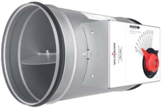
VR1 Volume Flow Controller
▶ Trust you can build in.
Product portfolio:
Areas of application for circular volume flow controllers and limiters
| Description | VR1 | VR1-N | VRL1 | VRE1 | VRup / VRpro |
| Functional principle | Mechanical controller | Mechanical controller | Mechanical limiter | Electronic controller | Electronic controller |
| Pressure difference | 50 .. 1000 Pa | 30 … 600 Pa | 30 … 300 Pa | 20 … 1000 Pa | 5 … 1000 Pa |
| Flow rate range | 50 … 3100 m³/h | 30 … 2300 m³/h | 13 … 1060 m³/h | 34 … 5430 m³/h | 42 … 5430 m³/h |
| Nominal diameter | DN 80 … DN 315 | DN 80 … DN 315 | DN 80 … DN 250 | DN 100 … DN400 | DN 100 … DN400 |
| Flow velocity | 2.1. 15.5 m/s | 1.1. 12.2 m/s | 0.8 … 6 m/s | 1.2 … 12 m/s | 1.5 … 12 m/s |
| Control accuracy | ±5 … ±10 % of set point flow rate | approx. ±5 % of nominal flow rate* | ±5 … ±10 % of nominal flow rate | ±5 … ±15 % of set point flow rate | ±5 … ±20 % of set point flow rate |
| Operating temperature | -20 … +70 °C, short-term 90 °C | -20 … +70 °C, short-term 90 °C | +10 … +50 °C | +5 … +60 °C | 0 … +50 °C |
| Further information | In this document | LINK | LINK | LINK | LINK |
* or ±10 % from set point flow rate (depending on which deviation is greater)
Product overview
VR1 volume flow controllers are maintenance-free, mechanically self-actuating controllers for supply air and exhaust air ducts with constant flow rates that operate without any auxiliary power supply. They are used especially at low flow velocities and variable pressures to keep the flow rate constant as per the set point value. The flow rate is set using a manual setting device with pointer, scale and locking mechanism. As an option, the VR1 can be fitted with a 24 V AC/DC or 230 V AC actuator for motorised set point adjustment for applications with variable flow rates.
- Highest control accuracy at variable pressures
- Factory preset for the set point flow rate
- Adjustable on site
- Position-independent installation
- Maintenance-free design
- Sizes DN 80 to DN 315
- Casing tightness: Class C as per DIN EN 1751
- Volume flow range: 50 … 3100 m³/h
- Pressure range: 50 … 1000 Pa
- Flow velocities: 2.1 … 15.5 m/s
- Temperature range: -20 … +70 °C, short-term +90 °C
- Hygiene certificate:
VDI 6022-1, VDI 3803-1, DIN 1946-4, DIN EN 16798-3, SWKI VA104-01, SWKI VA105-01, ÖNORM H6020, ÖNORM H6021 - Environment Product Declaration: EPD-WIL-20150036-ICA-EN
- Options
• Reversible actuator with 2-point and 3-point control for setting to two flow rate set points, 230 V AC or 24 V AC/DC
• Continuously adjustable reversible actuator for setting to any flow rate set point, 24 V AC/DC
• Acoustic insulation with sheet metal jacket
• SRC duct silencer in lengths: 600 mm and 900 mm
• Lip seals at both ends
Product features

1 Dimensions
| Nominal diameter [DN] | ||||||
| 80 | 100 | 125 | 160 | 200 | 250 | 315 |
2 Lip seal

For airtight connection to ventilation ducts
Optional accessories pre-assembled at the factory or for on-site installation
3 Set point adjustment
Manual (basic version)

Manual setting device with setting pointer, scale and locking mechanism:
The flow rate set point values are set manually using the setting pointer within the ranges ![]() . The controllers are adjusted at the factory for the entire volume flow range.
. The controllers are adjusted at the factory for the entire volume flow range.
The VR1 can be preset at the factory before delivery For this purpose, the flow rate set point values must be specified when ordering. Subsequent adjustment on site is possible.
Pre-installed at the factory before delivery
Actuator-driven (optional version)

M1:
Reversible actuator 230 V AC with 2-point and 3-point control.
The corresponding motor limit stops are positioned in order to adjust the flow rates.
Optional accessories pre-assembled at the factory or for on-site installation
M2:
Reversible actuator 24 V AC/ DC with 2-point and 3-point control.
The corresponding motor limit stops are positioned in order to adjust the flow rates.
Optional accessories pre-assembled at the factory or for on-site installation
M3:
Continuously adjustable reversible actuator 24 V AC/DC
To adjust the flow rates, a reference signal is used from 0 … 10 V.
Optional accessories pre-assembled at the factory or for on-site installation
For details, please refer to ▶ Page 16.
4 Accessories

Acoustic insulation with sheet metal casing to reduce the external sound radiation of the volume flow controller (radiated noise)
Optional accessories pre-assembled at the factory or for on-site installation
For details, please refer to ▶ Page 7.

SRC duct silencer for reducing flow noise in the connected ventilation duct. Packing thickness:
50 mm mineral wool lengths:
◼ 600 mm
◼ 900 mm
Optional accessories for on-site installation
For details, please refer to ▶ Page 7.
Product description
The VR1 volume flow controller is made of galvanised steel. The damper blade which controls the flow rate is centrally supported and has stainless steel bearing shafts in special bushes. The manual setting device is fitted with a setting pointer, scale and locking mechanism. Flow rate set points can be adjusted manually or by actuator within the flow rate ranges ![]()
The special control mechanism ensures high control accuracy, so with variable pressures, the flow rate can be kept constant over the entire pressure range.
The adjustable volume flow set points depend on the nominal diameter of the VR1.

| Item | Description |
| 1 | Duct casing |
| 2 | Label with scale and air direction indicator |
| 3 | Manual setting device with setting pointer, scale and locking mechanism |
| 4 | Lip seal (optional) |
| 5 | Acoustic insulation with sheet metal jacket (optional) |
| 6 | Damper blade |
| Size [DN] | ⩒min [m³/h] | ⩒max [m³/h] |
| 80 | 50 | 280 |
| 100 | 70 | 380 |
| 125 | 120 | 600 |
| 160 | 150 | 900 |
| 200 | 250 | 1300 |
| 250 | 400 | 2100 |
| 315 | 600 | 3100 |
3.1 Area of application
The VR1 volume flow controller is used in supply air and exhaust air ducts of ventilation and air conditioning systems.
Notes
- VR1 volume flow controllers are adjusted for the entire scaled application area.
- The flow rate set point is set during installation by turning the setting pointer to the desired value on the scale and locking this setting. This does not affect the control accuracy.
- Volume flow controllers that are preset at the factory can be installed directly. The flow rate set point can be changed at a later date by releasing the locking mechanism.
- The VR1 volume flow controller and the optional SRC duct silencer are supplied separately. Assembly is carried out on site.
- Installation and operating instructions for the VR1 are available on the Internet at www.wildeboer.de.
3.2 Function
The VR1 volume flow controller operates without any auxiliary power supply. The air flow in the ventilation duct generates a torque in the closing direction when it hits the damper blade. This torque is counterbalanced by the restoring torque of a blade spring so that the flow rate can be kept constant within the tolerances, even if the pressure differences change. Additional damping bellows ensures vibration-free movement of the damper blade.
3.3 Accessories
3.3.1 Acoustic insulation with sheet metal jacket
Acoustic insulation with a sheet metal jacket is supplied factory-mounted or for on-site installation.

Maximum possible reduction in radiated noise as a function of the nominal diameter:
| DN | Reduction |
| 80 | -18 dB |
| 100 | |
| 125 | |
| 160 | |
| 200 | |
| 250 | |
| 315 |
3.3.2 SRC duct silencer
The SRC duct silencer is supplied separately. Assembly is carried out on site along with the volume flow controller.

Packing thickness: 50 mm mineral wool
Maximum possible reduction in flow noise as a function of the silencer length:
| DN | Outer diameter [mm] | L [mm] | |
| 600 | 900 | ||
| 80 | 200 | -22 dB | – |
| 100 | 200 | -22 dB | -25 dB |
| 125 | 225 | -22 dB | -25 dB |
| 160 | 260 | -21 dB | -24 dB |
| 200 | 300 | -19 dB | -24 dB |
| 250 | 355 | -18 dB | -22 dB |
| 315 | 415 | -15 dB | -19 dB |
Quick dimensioning
The quick dimensioning table shows the expected sound power level of the VR1. Intermediate values can be interpolated for a rough estimate. The exact values for different differential pressures can be taken from the Wildeboer dimensioning software WiDim. ▶ WiDim
Sound level
| Size | Flow rate | Flow velocity | Differential pressure | Flow noise | Radiated noise |
| [DN] | ⩒ [m³/h] | v [m/s] | Dp [Pa] | Sound power level LWA [dB(A)] | Sound power level LWA [dB(A)] |
| 80 | 50 | 2.8 | 75 | 38.97 | <20 |
| 80 | 160 | 8.8 | 100 | 51.77 | 37.39 |
| 80 | 280 | 15.5 | 150 | 60.12 | 48.45 |
| 100 | 70 | 2.5 | 75 | 39.56 | <20 |
| 100 | 220 | 7.8 | 100 | 52.05 | 35.43 |
| 100 | 380 | 13.4 | 150 | 60.2 | 46.86 |
| 125 | 120 | 2.7 | 75 | 41.95 | 25.15 |
| 125 | 360 | 8.1 | 100 | 53.97 | 39.14 |
| 125 | 600 | 13.6 | 150 | 61.75 | 47.66 |
| 160 | 150 | 2.1 | 75 | 41.38 | 28.87 |
| 160 | 525 | 7.3 | 100 | 54.6 | 40.12 |
| 160 | 900 | 12.4 | 150 | 62.57 | 47.01 |
| 200 | 250 | 2.2 | 75 | 43.57 | 31.99 |
| 200 | 750 | 6.6 | 100 | 55.35 | 40.82 |
| 200 | 1300 | 11.5 | 150 | 63.37 | 47.74 |
| 250 | 400 | 2.3 | 75 | 45.41 | 29.98 |
| 250 | 1200 | 6.8 | 100 | 57.15 | 42.85 |
| 250 | 2100 | 11.9 | 150 | 65.22 | 50.6 |
| 315 | 600 | 2.1 | 75 | 46.66 | 32.67 |
| 315 | 1800 | 6.4 | 100 | 58.32 | 45.69 |
| 315 | 3100 | 11.0 | 150 | 66.2 | 53.41 |
The sound power level of the radiated noise can be further reduced by using acoustic insulation.
The mean sound pressure level in the room is:
- 26 dB lower with acoustic insulation
- 8 dB lower without acoustic insulation
than the sound power levels specified in the nomograms LWA.
The sound pressure level can be further reduced by carrying out additional sound attenuation measures on site (suspended ceilings, high degree of room attenuation).
However, the acoustic insulation can only achieve the stated values if connected ventilation ducts are also suitably soundproofed (insulated).
The sound power level of the flow noise can be reduced by up to 25 dB by using an SRC duct silencer. ▶ Page 7.
Installation
The VR1 volume flow controller is installed regardless of the position and in the air direction indicated on the label. To ensure lasting functionality and leak tightness, stress-free installation in ventilation ducts is a prerequisite.
Space requirement
To enable the scale to be read and the commissioning and servicing work to be carried out, sufficient space should be kept free in the area of any attachments. Inspection openings of sufficient size may required so that the attachments are easily accessible.
| Set point adjustment: manual | Set point adjustment: motorised |
 |
 |
5.1 Distances to disturbance points
The stated control accuracy of △⩒ applies to a straight and disturbance-free inflow. Fittings such as bends, branches or changes in cross-section cause turbulence that can influence the flow rate measurement.
For the VR1 volume flow controller to work optimally, the flows must be largely free of disturbance. After flow disturbance points (e.g. bends or branches), the straight inlet and outlet sections shown as examples must be observed; longer inlet sections may be required where several disturbance points occur consecutively. Otherwise significant control deviations must be expected.
Bend connection
Branch-off from main duct

The specified control accuracy of △⩒ can only be achieved with at least 3 x DN straight flow path.
Note:
EN 1506 must be observed for the design of ventilation duct connections.
Technical Data
| General data | |
| Nominal diameter | DN 80, DN 100, DN 125, DN 160, DN 200, DN 250, DN 315 |
| Flow rate range | 50 … 3100 m³/h |
| Control range | Approx. 18 … 100 % of nominal flow rate |
| Control accuracy | ±5 … ±10 % of set point flow rate |
| Differential pressure range | 50 … 1000 Pa |
| Flow velocity | 2.1. 15.5 m/s |
| Operating temperature | -20 … +70 °C, short-term +90 °C |
| Relative humidity | ≤ 95 %, non-condensing |
| Casing tightness as per DIN EN 1751 | Class C |
| Maintenance-free design | Yes |
| Materials | |
| Casing + damper blade | Galvanised steel |
| Bearing shafls | Stainless steel |
6.1 Dimensions

| Nominal diameter [DN] | 0d [mm] | L [mm] | L1 [mm] | X | AA [m²] |
| 80 | 79 | 329 | 40 | Manual: 65 mm Motorised: 130 mm |
0.005 |
| 100 | 99 | 329 | 40 | 0.008 | |
| 125 | 124 | 329 | 40 | 0.012 | |
| 160 | 159 | 329 | 40 | 0.020 | |
| 200 | 199 | 329 | 40 | 0.031 | |
| 250 | 249 | 407 | 60 | 0.049 | |
| 315 | 314 | 457 | 60 | 0.078 |
6.1.1 SRC duct silencer

| Size [DN] | Outer diam. [mm] | L [mm] | L1 [mm] | |
| 80 | 200 | 600 | – | 40 |
| 100 | 200 | 900 | ||
| 125 | 225 | |||
| 160 | 260 | |||
| 200 | 300 | |||
| 250 | 355 | |||
| 315 | 415 | |||
6.2 Weights
| Nominal diameter [DN] | VR1 [kg] | Acoustic insulation [kg] | Lip seal [g] | SRC duct silencer [kg] | |
| 600 mm | 900 mm | ||||
| 80 | 1.13 | 0.73 | 20 | 3.00 | – |
| 100 | 1.24 | 0.88 | 26 | 3.80 | 5.70 |
| 125 | 1.39 | 1.07 | 32 | 4.50 | 6.30 |
| 160 | 1.60 | 1.33 | 40 | 5.10 | 7.80 |
| 200 | 1.88 | 1.84 | 52 | 6.20 | 10.00 |
| 250 | 3.35 | 2.45 | 64 | 7.80 | 11.50 |
| 315 | 4.53 | 3.60 | 88 | 9.10 | 13.10 |
| Actuator | Weight [g] |
| M1 | 660 |
| M2 | 660 |
| M3 | 630 |
6.3 Sound power level (flow noise)
Sound power level L WA [dB(A)]

Sound power level L WA [dB(A)]


Nomenclature
| ⩒ | [m³/h] | Flow rate |
| AA | [m²] | Inflow cross-section |
| VA | [m/s] | Flow velocity in AA |
| △pS | [Pa] | Static pressure drop |
| △p | [Pa] | Differential pressure |
| LWA | [dB(A)] | A-weighted sound power level |
| LW-oct | [dB] | Octave sound power level LW-oct = LWA + DL |
| △L | [dB] | Relative sound power level to LWA |
| f | [Hz] | Octave mid-frequency |
| Lp | [dB] | Sound pressure level |
| LpA | [dB(A)] | A-weighted sound pressure level |
Example:

- The sound power levels of the flow noise can be further reduced by using the SRC duct silencer. Further information ▶ Page 7
- The sound power levels inside the connecting duct are calculated in the nomograms as A-weighted overall levels LWA.
- Corresponding octave sound power levels LW-oct for each size and for all operating points are derived from the Wildeboer dimensioning software ▶ WiDim; likewise the dimensioning with additional SRC duct silencer.
- Important: The sound levels indicated in the nomograms are stated as sound power levels! They represent the sound energy introduced into the duct system. They are used for acoustic calculations, e.g. when adding sound attenuators.
- Please note: In many cases, the sound pressure levels Lp or LpA are specified, which give attenuations of up to 16 dB. When comparing numerical values, always bear in mind the difference between the sound power level and sound pressure level. Furthermore, the degree of attenuation is only obtained with specific connected ducts, deflections, branches and rooms.
6.4 Sound power level (radiated noise)
Sound power level LWA [dB(A)]


- The sound power levels of the radiated noise can be further reduced by using acoustic insulation. Further information ▶ Page 7
- The sound pressure level can be further reduced by carrying out additional sound attenuation measures on site (suspended ceilings, high degree of room attenuation).
Nomenclature
6.5 Set point adjustment
6.5.1 Manual
In the basic version, VR1 volume flow controllers are designed for manual adjustment of the flow rate set point and operate without any auxiliary power supply. The volume flow set point is preselected on an adjusting device and, with variable pressures, is kept constant to a high degree of accuracy. The volume flow controllers are adjusted at the factory for the entire volume flow range.
6.5.2 Motorised
As an option, the set point adjustment can be motorised via factory-mounted electric actuators. Reversible actuators and continuously controllable reversible actuators are available for this.

Reversible actuators (M1, M2) open and close the volumetric flow controllers with 230 V AC voltage or 24 V DC or AC voltage.
The M1 (230 V AC) and M2 (24 V AC/DC) actuators enable 2-point and 3-point control. The corresponding motor limit stops are positioned in order to adjust the two flow rates. As delivered, the two limit stops of the actuators are set to the 0 direction of travel and the largest possible angle of rotation. The maximum angle of rotation corresponds to the largest possible flow rate set point, and the minimum is equivalent to a “cutoff” at a residual leakage that is significantly lower than the minimum flow rate. This can be extended to give 3-point control using an additional 0 circuit arrangement.
When operated in this way, the actuator remains in its current position and the VR1 volume flow controller adjusts the corresponding set point.
Continuously adjustable reversible actuator (M3) with 24 V AC/DC sets the volume flow controllers to any desired position.
The position is specified by means of a command signal of 0 or 2 to 10 V, position feedback via an output signal of 2 to 10 V.
The M3 (24 V AC/DC) actuator enables continuous set point adjustment. The actuator is controlled with a setting voltage of Y = 0 … 10 V DC and moves to the position specified by the control signal; however, the operating range of the motor only starts at 2 V. The flow rate set point changes almost linearly with the setting voltage. As delivered, the actuator is set to 0 direction of travel and the adjustable mechanical limit stops are set for the largest possible angle of rotation, which means that when Y = 10 V, the maximum angle of rotation corresponds to the maximum volume flow set point, and at 0…2 V the minimum angle of rotation is approached; this corresponds to a “cutoff” at a residual leakage that is significantly lower than the minimum volume flow set point. The purpose of the checkback voltage U = 2 … 10 V DC is to provide an electric indication of the volume flow set point setting and to serve as a subsequent actuating signal for other actuators.
Notes
- All the actuators are overload-proof, do not require limit switches, and stop automatically at the limit stop.
- In the event of a power failure or interruption, the current actuator position is retained.
- The direction of travel of all the adjusting actuators can be reversed via a pushbutton on the motor.
Presetting
Depending on the nominal diameter, the flow rate set point can be preset at the factory in the following increments.
| Nominal diameter [DN] | Flow rate set pointmin | Flow rate set pointmax | Increments |
| 80 | 50 | 280 | 10 |
| 100 | 70 | 380 | 10 |
| 125 | 120 | 600 | 20 |
| 160 | 150 | 900 | 25 |
| 200 | 250 | 1300 | 50 |
| 250 | 400 | 2100 | 100 |
| 315 | 600 | 3100 | 100 |
Electrical connection
| M1: 2- point control | M1: 3- point control |
 |
 |
| M1: Direction of travel | M2: 2- point control |
 |
 |
| M2: 3- point control | M2: Direction of travel |
 |
 |
| M3: Continuous control | M3: Direction of travel M3: Direc |
 |
 |
Specification text
Maintenance-free, circular volume flow controller for position-independent installation in circular ventilation ducts for supply and exhaust air in ventilation and air conditioning systems. Casing and control mechanism made of galvanized sheet steel, with acoustic insulation, with lip seals. With centrally supported damper blade for volume flow control, with stainless steel bearing shaft in special bushes. Adjustment device with rotary pointer, scale and locking device for the volume flow set point, can be adjusted manually or by actuator. Volume flow controller designed as mechanical controller for constant volume flows without any auxiliary power supply. With special control mechanism for a high degree of control accuracy throughout the entire control range. The volume flow set point must be infinitely adjustable throughout the control range. With variable pressures between 50 and 1000 Pa, the volume flow must be kept constant with a deviation of roughly ±5 % to ±10 %. Casing tightness class C as per DIN EN 1751. Certificate as proof of compliance with the hygiene requirements as per VDI 6022-1, VDI 3803-1, DIN 1946-4, DIN EN 16798-3, SWKI VA104-01, SWKI VA105-01, ÖNORM H6020 and ÖNORM H6021. With Environmental Product Declaration as per ISO 14025 and EN 15804.
…….. pcs.
Volume flow: ……… m³/ h
Press uredrop: ……… P a
Maximum sound power level
Flow noise ……… d B(A)
including SRC duct silencer
Radia tednoise ……… d B(A)
Manufacturer: WILDEBOER
Type: VR1
Size: ………
Complete with fixing sdelier:……….
install: ………. ……….
…….. pc. SRC 600 / 900 duct silencer
deliver: ……….
install: ………. ……….
Delete text not printed in bold as required!
You can find this tender text on the website www.ausschreiben.de ▶ ausschreiben.de.
Or you can use the specification text customised for your product selection in the Wildeboer Configurator ▶ Wildeboer Configurator.
Wildeboer makes it easy
8.1 Wildeboer Configurator

- Quick, intuitive configuration of Wildeboer products
- Easy calculation of operating point data for the configured product
- 3D display of the product and download in various formats
- Download of data sheets, specification texts and version keys
- Login area with individual price display option
 https://app.wildeboer.de/prdcfg/prodgroups?path=3.20.31
8.2 WiDim dimensioning software

- Functional, modern and intuitive dimensioning of Wildeboer products
- Conveniently collect operating point data, 3D product views, suitable accessories and current revision documents in a single project
- Project can be output in various formats
- A GAEB interface and an interface based on VDI 3805 facilitate a continuous planning process
 https://www.wildeboer.de/de/service/widim-dimensionierung/
8.3 Documents online

- Paperless and environmentally friendly online access to Wildeboer documents
- All documents in one central location and always up to date
- Supporting interactive formats and content
 https://www.oxomi.com/p/2025288/
▶ Always there for you
Locations & contact

Factory – Administration
+49 4951 950-0
info@wildeboer.de
www.wildeboer.de
Utrecht office
+31 30 767 0150
info@utrecht.wildeboer.eu
www.wildeboer.de/nl
Ulm office
+49 7392 9692-0
info@ulm.wildeboer.de
www.wildeboer.de
Leipzig office
+49 34444 310-0
info@leipzig.wildeboer.de
www.wildeboer.de

![]() Find out more at
Find out more at
www.wildeboer.de/downloads
Documents / Resources
 |
WILDEBOER VR1 Volume Flow Controller [pdf] User Manual VR1 Volume Flow Controller, VR1, Volume Flow Controller, Flow Controller, Controller |