![]() Owner’s Manual
Owner’s Manual
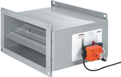
VK2 Volume Flow Controller
Option
with sound attenuator
Maintenance-free
VK2 Volume Flow Controller
for ventilation and air conditioning systems.
■ Adjustable on site.
■ Outstanding control accuracy.
■ Sizes B x H = 200 x 100 to 600 x 300.
■ Casing tightness class C as per DIN EN 1751.
Overview

With the basic version of the VK2 volume flow controller, the volume flow set point is adjusted manually.
The controllers operate without any auxiliary power supply!
The volume flow set point is preselected on an adjusting device with scale and, with variable pressures, is kept constant to a high degree of accuracy. The controllers are adjusted at the factory for the entire volume flow range.
- The volume flow set point is easy to adjust on site!
- The volume flow set point can be preset at the factory if requested when ordering. Subsequent changes are easy to do on site. ⇒ see page 7
Option
VK2 volume flow controller with actuator-driven adjustment of the volume flow set point.
Depending on which actuator is selected, two set points or any intermediate values are possible.
Can be used in systems with variable volume flows, for example with day/night changeover or fully variable load-dependent operation.

Option
VK2 volume flow controller with acoustic insulation for thermal protection and reduction of external sound radiation.
Can be used for controllers with manual and motorised setting of the required volume flow!

Option
SKB-V sound attenuators for volume flow controllers for reducing internal flow noise. Sound attenuator length 1500 mm.
Maximum possible reduction of flow noise in [dB] with a

Description, sizes, technical data

VK2 volume flow controllers are maintenance-free mechanical controllers that operate without any auxiliary power supply to maintain constant volume flows in ventilation and air conditioning systems.
They are installed in supply and exhaust air ventilation ducts and are not position-sensitive. The casing and control mechanism are made of galvanized sheet steel. The damper blade for volume flow control is centrally supported and guided in special bearing bushes, with stainless-steel shafts. The setting device is equipped with a rotary pointer, scale and locking device. The volume flow set points can be adjusted manually or by actuator within the volume flow ranges ![]()
The special control mechanism ensures a high degree of control accuracy with a deviation of only approx. ± 5% to ± 15%*). This means that, with variable pressures, the volume flow is kept constant throughout the entire pressure range.
- Sizes B x H x L: as shown in table opposite
- Overall volume flow range: V min =200toVmax =7000m³/h
- Pressure range: 50 to 1000 Pa ⇒ see page 4
- Casing tightness: Class C as per DIN EN 1751
- Interior temperature range: -20 to +70°C, up to 90°C for a short time only
- Options
- Actuator-driven setting to two volume flow set points, 230 V AC or 24 V AC/DC.
- Continuous actuator 24 V AC/DC, setting to any desired volume flow set point
- External acoustic insulation with sheet metal jacket
- Factory preset for volume flow set point ⇒ see page 7
- SKB-V sound attenuator for volume flow controller
| Width W [mm] |
Height H [mm] |
Length L [mm] |
Inflow cross-section AA [m2] |
Volume flow | |
| Vmin [m3/h] | Vmax [m3/h] | ||||
| 200 | 100 | 300 | 0.020 | 200 | 800 |
| 150 | 325 | 0.030 | 250 | 1200 | |
| 200 | 425 | 0.040 | 350 | 1550 | |
| 300 | 100 | 300 | 0.030 | 250 | 1200 |
| 150 | 325 | 0.045 | 350 | 1650 | |
| 200 | 350 | 0.060 | 500 | 2100 | |
| 250 | 450 | 0.075 | 600 | 2800 | |
| 300 | 500 | 0.090 | 750 | 3500 | |
| 400 | 200 | 375 | 0.080 | 700 | 3300 |
| 250 | 450 | 0.100 | 800 | 3700 | |
| 300 | 500 | 0.120 | 1000 | 4250 | |
| 500 | 200 | 375 | 0.100 | 875 | 4125 |
| 250 | 400 | 0.125 | 1000 | 4375 | |
| 300 | 500 | 0.150 | 1200 | 5200 | |
| 600 | 200 | 350 | 0.120 | 1125 | 4750 |
| 250 | 500 | 0.150 | 1400 | 6000 | |
| 300 | 500 | 0.180 | 1600 | 7000 | |
Control deviations stated as a percentage relatetotheselectedvolumeflowsetpoint.
VK2 Volume Flow Controller
- satisfy the hygiene requirements as per VDI 6022-1, VDI 3803-1, DIN 1946-4, DIN EN 16798-3, SWKI VA104-01, SWKI VA105-01, ÖNORM H6020 and ÖNORM H6021.
- are resistant to microbes, so they do not promote the growth of microorganisms (fungi, bacteria). This reduces the infection risk for people, and also means less cleaning and disinfection work!
- are resistant to cleaning agents and disinfectants, and are suitable for use in hospitals and similar facilities!
- With Environmental Product Declaration as per ISO 14025 and EN 15804: EPD-WIL-20150037-ICA1-EN.
www.HYG.de www.wildeboer.de!
Sound power level in the connecting duct (flow noise)

Example:

- The sound power level inside the connecting duct is calculatedinthenomogramsasanA-weightedoverall level LWA.
Corresponding octave sound power levels LW-Oct can be calculated for every size and all operating points using the Wildeboer dimensioning software; also for designs with additional SKB-V sound attenuator. - With SKB-V sound attenuators, the sound power levels LWA can be reduced by up to 13 dB.
- Important: The sound levels indicated in the nomograms are stated as sound power levels! They represent the sound energy introduced into the duct system.They are used for acoustic calculations, e.g. when adding sound attenuators.
Please note: In many cases, the sound pressure levels Lp or LpA are specified giving general attenuations of up to 19 dB. When comparing numerical values, always bear in mind the difference between the sound power level and sound pressure level.
Furthermore, the degree of attenuation is only obtained with specific connected ducts, deflections, branches and rooms.

Sound power level outside the connecting duct (radiated noise)


- 14 dB lower with acoustic insulation
- 8 dB lower without acoustic insulation
However, the acoustic insulation can only achieve the stated values if connected ventilation ducts are also suitably soundproofed (insulated).
The sound pressure level can be further reduced by carrying out additional sound attenuation measures on site (suspended ceilings, high degree of room attenuation).

Technical data for adjustment actuators, installation instructions
| M1 | M2 | M3 | |
| Supply voltage | 230 V AC | 24 V AC/DC | 24 V AC/DC |
| Function range | 85 to 265 V | 19.2 to 28.8 V | 19.2 to 28.8 V |
| Run time for 90° | 150 s | 150 s | 150 s |
| Connected load | ≤ 6 VA | ≤ 4 VA | ≤ 4 VA |
| Power consumption | ≤ 2.5 W | ≤ 2 W | ≤ 2 W |
| Protection rating | IP 54 | IP 54 | IP 54 |
| Connection cable approx. 1 m long 0.75 mm² | 3-core | 3-core | 4-core |
| Ambient temperature | -30 to +50 °C | -30 to +50 °C | -30 to +50 °C |
Adjusting actuator M1

Adjusting actuator M2

Adjusting actuator M3

Installation instructions
- VK2 Volume flow controllers are adjusted for the entire scaled application area.
- To install the controllers, a straight inlet section at least 3 times as long as the nominal width W and a straight outlet section at least 1.5 times as long as nominal width are required. Installation directly downstream or upstream of flow disturbance points (bends, branches, etc.) reduces the control accuracy.
- The volume flow set point is adjusted during installation. This does not affect the control accuracy.
- The basic version is adjusted manually by setting the pointer to the required set point on the scale and fixing this setting.
- Dual controller: If the duct cross-section is larger than the available controller size, two or more VK2 volume flow controllers can be installed in parallel. The volume flow must be distributed in such a way that each controller is configured to the same flow velocity. Suitable metal plates for connecting the flanges and compensating for differences in length must be provided on site. Sound power levels must be added together.
- VK2 volume flow controllers and SKB-V sound attenuators are supplied individually. Assembly on site!
- Volume flow controllers with actuator-driven adjustment enable two-point operation (single-wire control) in combination with the actuators M1 (230 V AC) and M2 (24 V AC/DC). The corresponding motor limit stops are positioned in order to adjust the two flow rates.
As delivered, the two limit stops of the actuators are set to the 0 direction of travel and the largest possible angle of rotation. The maximum angle of rotation corresponds to the largest possible volume flow set point, and the minimum is equivalent to a “cutoff” at a residual leakage that is significantly lower than the minimum volume flow as specified in the catalogue.
This can be extended to include three-point operation using an additional 0 circuit arrangement (two-wire control). When operated in this way, the actuator remains in its current position and the VK2 volume flow controller adjusts the corresponding set point. - Volume flow controllers with actuator-driven adjustment in combination with the actuator M3 (24 V AC/DC) enable continuous adjustment of the set point. The actuator is controlled with a setting voltage Y of DC = 0…10 V, and moves to the position specified by the control signal; however, the operating range of the motor only starts at 2 V. The flow rate set point changes almost linearly with the setting voltage.
As delivered, the actuator is set to 0 direction of travel and the adjustable mechanical limit stops are set for the largest possible angle of rotation, which means that when Y = 10 V, the maximum angle of rotation corresponds to the maximum volume flow set point, and at 0…2 V the minimum angle of rotation is approached; this corresponds to a “cutoff” at a residual leakage that is significantly lower than the minimum volume flow set point.
The purpose of the feedback voltage U = 2…10 V DC is to provide an electrical indication of the volume flow set point setting and to serve as a subsequent actuating signal for other actuators. - All the actuators are overload-proof, do not require limit switches, and stop automatically at the limit stop.
- All the actuators can be equipped with a self-resetting pushbutton to allow manual adjustment.
- The direction of travel of all the actuators can be reversed via a changeover switch on the motor.
- In the event of a power failure, the motor remains in its current position and the controller controls the corresponding set point.
- Installation instructions are enclosed with the volume flow controllers and must be followed!
Ordering data, specification text
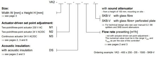
Select texts not highlighted in bold as required!
Maintenance-free, rectangular volume flow controller for position-independent installation in ventilation ducts for supply and exhaust air in ventilation and air conditioning systems. Casing and control mechanism made of galvanized sheet steel, with acoustic insulation. With centrally supported damper blade for volume flow control, with stainless steel bearing shaft in special bushes. Adjustment device with rotary pointer, scale and locking device for the volume flow set point, can be adjusted manually or by actuator. Volume flow controller designed as mechanical controller for constant volume flows without any auxiliary power supply. With special control mechanism for a high degree of control accuracy throughout the entire control range. The volume flow set point must be infinitely adjustable throughout the control range. With variable pressures of between 50 and 1000 Pa, the volume flow must be kept constant with a deviation of roughly ±5% to ±15%. Casing tightness class C as per DIN EN 1751. Certificate of conformity as proof of compliance with the hygiene requirements as per VDI 6022-1, VDI 3803-1, DIN 1946-4, DIN EN 16798-3, SWKI VA104-01, SWKI VA105-01, ÖNORM H6020 and ÖNORM H6021. With Environmental Product Declaration as per ISO 14025 and EN 15804.

INNOVATIVE ● PRACTICAL ● ECONOMICAL

TAKE ADVANTAGE OF OUR STRENGTHS!![]() COMPONENTS FOR VENTILATION + AIR CONDITIONING
COMPONENTS FOR VENTILATION + AIR CONDITIONING
air distribution fire protection noise protection
building control systems
© 2004 … 2020 WILDEBOER BAUTEILE GMBH D26826 WEENER,
GERMANY
Documents / Resources
 |
WILDEBOER VK2 Volume Flow Controller [pdf] Owner's Manual VK2-1220, VK2 Volume Flow Controller, VK2, Volume Flow Controller, Flow Controller, Controller |