WATTS OneFlow Ge-Mini Compact Anti Scale System
INTRODUCTION
One Flow® Ge-Mini is an anti-scale system to be installed on cold water line, upstream to equipment and piping to be protected. Due to its compactness, it can be installed below the sink or in very small technical rooms.
One Flow® uses innovative technology to trap the minerals that cause hard water and convert them into inert microscopic crystals, which remain suspended in the water until they are expelled. The system is extremely easy to maintain and does not require any backwashing, salts or electricity.
It neutralises the damaging effects of hard water, especially the build-up of scale in heating elements, pipes, water heaters and boilers.
One Flow® is not a water softener and does not require the addition of chemicals. It is a device for preventing the buildup of hard scale, and its effectiveness has been proven by independent laboratory tests and years of successful use in residential, commercial and catering applications. One Flow® is an intelligent anti-scale solution that provides the ideal alternative to water softening systems and chemical treatment.
- One Flow® converts hardness minerals into inert microscopic crystals, and is therefore an effective alternative to conventional water softeners.
- Low maintenance: no salts or chemical additives required
- No electricity needed
- Helps reduce water and electricity consumption, does not require control valves.
- Innovative technology for a more eco-friendly approach, without using salts or chemical additives.
- Improves the efficiency of all heating devices and plumbing system components.
- The ideal solution for protecting domestic appliances, maximising their service life and reducing energy consumption.
- One Flow® cartridge systems are extremely easy to maintain: simply change the cartridges every two years.
SYSTEM SPECIFICATIONS
Inlet and outlet connections: BSP 3/4” threaded fittings
One Flow® Ge-Mini: Maximum flow up to 23L/min
Maximum pressure: 6 bar
Maximum temperature: 38°C
Minimum temperature: 5°C
Weight: 3,7 kg
Capacity: The cartridges do not have a grain removal capacity; however, other elements found in the water will gradually impair their effectiveness. Change the cartridges at least once every two years.
Install the One Flow® scale control system on the cold water line, upstream of the network/system to be treated. The system must be sized on the basis of the peak or rated flow, as indicated in the specifications for the device in question.
The One Flow® system can also be installed to protect multiple appliances against the damaging effects of scale and hard water, taking care to check the total peak flow of the devices to be protected. Install a bypass so that the system can be isolated when performing maintenance or changing the cartridge. The bypass is recommended but not mandatory.
Install the system in an area that is large enough to make it possible to carry out maintenance operations. Once activated, the One Flow® system does not waste water on backwashing, flushing or regeneration and does not require chemical additives or electricity to operate.
FEED WATER CHEMISTRY REQUIREMENT
| pH | 6.5-8.5 |
| Hardness (maximum) | 28.8°dH, 51.3°F (513 mg/L CaC03)* |
| Water pressure | 1.03 to 6 bar |
| Temperature | 5 to 38°C |
| Free chlorine | <2 mg/L |
| Iron (maximum) | 0.3 mg/l** |
| Manganese (maximum) | 0.05 mg/l** |
| Copper | 1.3 mg/l** |
| Oil and H2 S | must be removed in advance |
| Total phosphates | < 3.0 mg/I |
| Silica (maximum) | 20 mg/l† |
| TDS | 1500 mg/L†† |
These chemical specifications correspond to the averageparameters of the normal water supply. Contact your local water company to check the specifications of the water.
Note
- Systems using One Flow® technology are effective at preventing scale formation in plumbing systems at significant hardness levels of up to 513 mg per litre (28.8°D, 51.3°F) of calcium carbonate. Due to variations in the chemical specifications of water, the maximum recommended hardness is 513 mg/L, in order to avoid potential cosmetic problems caused by the formation of traces of scale on the outside of pipes.
- As with conventional water softening media, One Flow® granules need to be protected from excess levels of certain metals that can easily coat the active surface, reducing effectiveness over time. Water from the public mains does not pose this problem, except in rare cases; if you are using water from a private well, however, check that the levels of iron (Fe) and manganese (Mn) are below 0.3 mg/L and 0.05 mg/L respectively. Also check that the levels of copper (Cu) are below 1.3 mg/L at all times.
† One Flow® systems do not reduce silica scaling. While silica tends to have a less significant effect on scale formation than other minerals, it can act as a binder that makes water spots and limescale residue difficult to remove from the outside of plumbing system components. This 20 mg/l limitation is for aesthetic purposes.
†† All other water contaminants must meet the requirements set down by the water regulatory authority in the country where One Flow® is sold and installed. The maximum level of contamination by specific minerals and metals, classified in the above chemical specifications of the water supply, replaces the aforementioned requirements. If the water contains excessive quantities of impurities and debris, ensure that it is pre-filtered before using One Flow®.
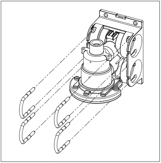
INSTALLATION
The cutting-edge modular technology of this antiscale system allows for full system customization at the installation site.
To aid with installation, each manifold includes a built-in level indicator to ensure proper installation.
Recommendations
- Read instructions completely before proceeding with the installation.
- Allow a minimum 10 cm clearance from base system to allow for cartridge change outs.
- The system may be installed using metal or non-metallic piping systems.
- The mounting hardware used must be selected and installed so that the system is firmly attached to the mounting surface.
The system mounting hardware must keep the system from moving during routine service and operation. - System and installation must comply with applicable state and local regulations.
- Use system on cold water source only.
- Do not use with water that is microbiologically unsafe or of unknown quality without adquate disinfection before or after the system.
- System must be installed in a vertical, upright and level position.
- If water is known to have presence of debris and sediments it is recommend to install a filter (WHOF1 or WHOF2) upflow.
- Do not install the unit outside, do not allow system to freeze, and do not install directly in contact with sunlight.
- Install a shut-off valve upstream and downstream from the One Flow® device so that it can be isolated for maintenance or provide a by-pass.
- Do not perform welding on the head connection unions.
High temperatures may damage or deform the product. - Avoid use in closed circuits (e.g. hydronic systems), low flow installations or with standing water (max. 72 to 120 hours, depending on the quality of the incoming water).
- If there is a risk of water hammer, install a water hammer arrestor.
- If there is a risk of inlet pressure peaks, install a pressure reducing valve before One Flow®.
Operations
- Shut down all equipment downstream of the system installation site and turn off the water supply.
- Using the mounting holes in the manifold as a guide, mark and drill pilot holes for the mounting bolts.
- It is recommended to provide a by-pass to the unit, to simplify maintenance and cartridges replacement.
NOTE: System must be installed in vertical, up- right, and level position. - Connect incoming cold water line to inlet port of the manifold connection (marked with IN).
NOTE: Use Teflon™ tape only. Do not use paste type thread sealant. - Connect the outlet port to the equipment system line (marked with OUT)
- Install the filters into the manifold by inserting them into the manifold head and swiftly turning them a quarter turn to the right (clockwise) until they are fully seated.
NOTE: Remove all plastic wrapping and dust caps prior to filter installation. - Write the date the filter was installed in the designated box on the filter canister.
NOTE: The flush line should NOT be hard plumbed into the drain.
Modular design
- Manifold has a modular design that can help during maintenance operations and create different configurations.
For One Flow® Ge-Mini only factory configuration is available. - Grey U Clips keeps the parts that composed the manifold safely in position during its working. Do not remove them.
- Grey inserts on the back of manifold are blocking elements for the parts, please do not remove them.
- In case of damage of the IN/OUT connection, it is possible to remove grey U Clips close to connection, dislodge connection and replace it with a new one.
System startup
- Check all connections to make sure they are secure, including all U Clips at each fitting on the manifold assembly.
- Open the flush ball-valve on the filtration system ensuring the drain tubing is directed to a drain or a container.
- Turn on the water supply to the system.
- Flush the cartridges by running water for five minutes through the system. This will purge any trapped air and fines.
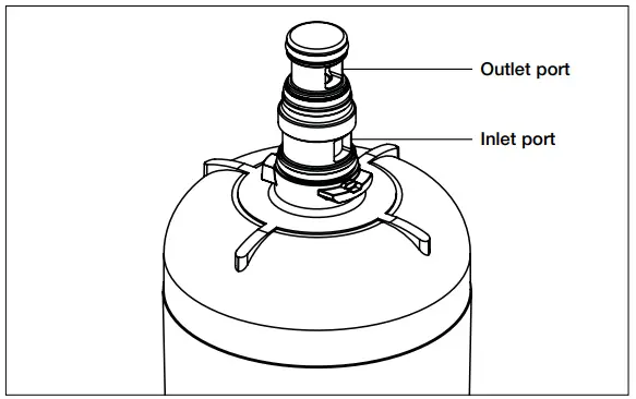
Figure 3. CARTRIDGE PORTS/INTERFACES
NOTE: The system is equipped with a unique patented Bypass Indicator System (BIS), which can indicate if there is an issue with the cartridge. For more information about the BIS, refer to the Maintenance section of this manual. During the initial startup of the system, a slight amount of water may weep out of the BIS ports (Figure 4). This is typical during system pressurization phase.
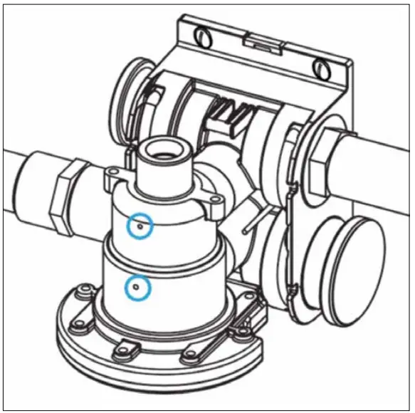
Figure 4. BYPASS INDICATOR SYSTEM - Close the flush ball-valve and turn on power to equipment.
- Check for leaks.
MAINTENANCE
Routine maintenance of this system involves periodic filter changes. The manufacturer recommends regularly scheduled maintenance and replacement of filter cartridges every 2 years maximum, in order to ensure optimum performance of the system and equipment that it services.
Cartridges could be replaced earlier depending upon antiscaling efficiency reduction, which may occur due to the incoming water quality. The manufacturer shall not be liable for equipment failure due to improper maintenance of poor water quality.
Removing a cartridge
- Holding the cartridge with both hands, swiftly rotate the cartridge quarter turn to the left until disengaged. The inlet water will automatically shut off (Figure 5).
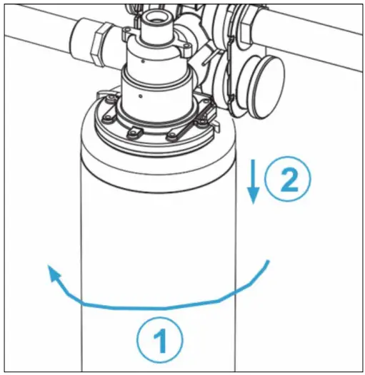
Figure 5. REMOVING CARTRIDGE - Discard old cartridge.
Installing a cartridge
- Install the filter into the manifold by inserting it into the manifold head and swiftly turning it quarter turn to the right (clockwise) until it fully seated (Figure 6).
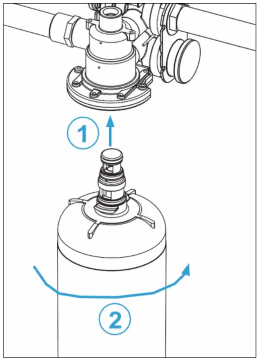
Figure 6. INSTALLING CARTRIDGE
NOTE: Remove all plastic wrapping and dust caps prior to filter installation. - Write the date the filter was installed in the designated box on the filter canister.
NOTE: A small amount of water may weep out of the BIS indicator ports while the filtration system pressurizes. - Check the system for leaks.
- Flush the cartridge(s) by running water for five minutes through the system. This will purge any trapped air and fines from the system.
BYPASS INDICATOR SYSTEM
OVERVIEW
The system is equipped with a unique patented By-pass Indicator System (BIS), which can indicate if there is an issue with the cartridge. If there is an issue with the cartridge, water will slowly but continuously weep out of one of the two ports.
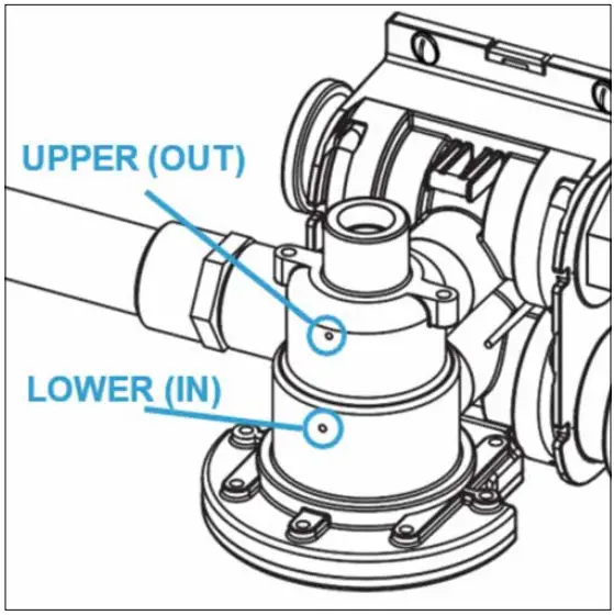
Figure 7. BYPASS INDICATOR SYSTEM
Upper (OUT) and lower (IN) ports
If water weeps out of the BIS Upper Port, there is a failure with the cartridge’s O-Ring. Inspect and replace the O-Ring as needed.
If water weeps out of the BIS Lower Port, there is an internal failure with the cartridge. For example, if a cartridge suffers carbon block damage during transit or handling, a small amount of water will slowly but continuously weep out of the BIS Lower Port on the head assembly. In this case, a new cartridge must be installed.
TROUBLESHOTING
| Problem | Cause | Corrective Action |
| No water comes out of the water filter system. | Filter(s) are plugged. | Replace filter(s). |
| Vapor-lock. | Rinse system. | |
| Low flow from the water filter system. | Filter(s) are plugged. | Replace filter(s). |
| Vapor-lock. | Rinse system. | |
| Filter leaks from filter interface. | O-Ring is out of position in gland. | Inspect O-Ring and set in gland. |
| Nicked or cut O-Ring(s) on filter. | Replace O-Ring or filter. | |
| Missing O-Ring(s) | Install O-Ring(s). | |
| Water comes out of the upper Bypass Indicator System port. | O-Ring is out of position in gland. | Inspect O-Ring and set in gland. |
| Nicked or cut O-Ring(s) on filter. | Replace O-Ring or filter. | |
| Missing O-Ring(s). | Install O-Ring(s). | |
| Water comes out of the lower Bypass Indicator System port. | Broken filter | Replace filter(s). |
| Water leaks from fittings. | O-Ring is out of position in gland. | Inspect O-Ring and set in gland. |
| Nicked or cut O-Ring(s) on fitting. | Replace O-Ring or filter. | |
| Missing O-Ring(s). | Install O-Ring(s). | |
| Water leaks from back of manifold/wall. | O-Ring is out of position in gland. | Inspect O-Ring and set in gland. |
| Nicked or cut O-Ring(s) on fitting. | Replace O-Ring or filter. | |
| Missing O-Ring(s). | Install O-Ring(s). |
The descriptions and photographs contained in this product specification sheet are supplied by way of information only and are not binding. Watts Industries reserves the right to carry out any technical and design improvements to its products without prior notice.”
Warranty: All sales and contracts for sale are expressly conditioned on the buyer’s assent to Watts terms and conditions found on its website at www.watts.eu Watts hereby objects to any term, different from or additional to Watts terms, contained in any buyer communication in any form, unless agreed to in a writing signed by an officer of Watts.
CUSTOMER SUPPORT
Guarantee
Watts products are thoroughly tested. The said guarantee covers solely replacement or – at the full sole discretion of WATTS – repair, free of charge, of those components of the goods supplied which in the sole view of Watts present proven manufacturing defects. The period of limitation for claims based on defects and defects in title is two years from delivery/the passage of risk. This warranty excludes any damage due to normal product usage or friction and does not include any modified or unauthorized repair for which Watts will not accept any request for damage (either direct or indirect) compensation (for full details see our website). All sales subject to the Watts terms to be found on www.watts.eu/uk.
Watts Industries Italia S.r.l.
Sede operativa: Via Brenno, 21 – 20853 Biassono (MB), Italia
Tel: +39 039 49.86.1
Sede legale: Frazione Gardolo, Via Vienna, 3 – 38121 Trento (TN), Italia – Cod. Fisc. 00743720153 – Partita IVA n° IT 01742290214
Società unipersonale del gruppo Watts Italy Holding Srl – soggetta a direzione e coordinamento ai sensi degli artt. 2497 e s.m.i. del C.C.
OFGE-MINI-IOM-UK-W-UK-04-25-Rev0
© 2025 Watts

Documents / Resources
 |
WATTS OneFlow Ge-Mini Compact Anti Scale System [pdf] Instruction Manual OneFlow Ge-Mini Compact Anti Scale System, OneFlow Ge-Mini, Compact Anti Scale System, Anti Scale System, Scale System |