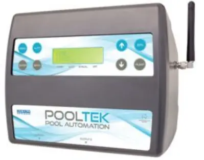
Waterco AQUASMART 5 Pooltek Pool Automation
Specifications:
- Master Controller Max Current Load: 9.9 Amps / 2370 Watts
- 10Amp Expansion Unit Max Current Load: 9.9 Amps / 2370 Watts
- 15Amp Expansion Unit Max Current Load: 14.9 Amps / 3570 Watts
Installation & Setup:
Master Controller & Expansion Unit/s Installation:
Install the controller out of direct weather conditions. Do not turn on the power until all criteria are met.
App Installation:
Download the Pooltek app from Playstore for Android or App Store for iPhones. Scan the QR code on the Master Controller after installing the app. Ensure 2.4Ghz wifi band is enabled.
Heater Installation:
If the heater’s flow or pressure switch circuit is 240Vac,purchase and install an external relay (KIT10 or KIT11) by a licensed electrician.
Usage Instructions:
Connecting Equipment:
Follow the wiring instructions to connect Master Controller,Expansion Units, and Pooltek Chem Doser.
Variable Speed Pump Connection:
Refer to the manual for specific pump models and required communication cables for connection.
Setting Up Pump Control:
For Waterco ECO-V pumps, use the Pooltek Speed Control function.
Insert control cable wires into the pump control terminal block following the specified color order.

FEATURE
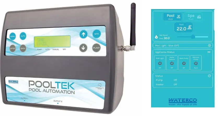
Owning a swimming pool and spa has never been easier or more enjoyable thanks to Waterco Pooltek Pool Automation, one of the most versatile and easy to use controllers on the market. Control Pooltek through the app allowing full remote control of your pools single and multispeed pumps, sanitiser, heater, solar heating, lights, water features, pool/spa valve actuators and all spa equipment requirements. Modular and expandable to meet the needs of new and existing pools, the system is easily retrofitted to existing pool / spa equipment and has an option for ORP and pH monitoring and dosing.
Installation & Setup
Master Controller & Expansion Unit/s Installation
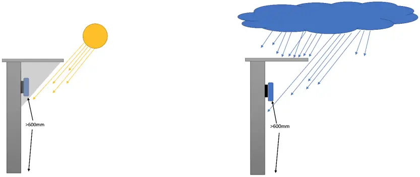
Ideally, as with all pool equipment, the controller should be installed out of direct weather.
- Find a suitable location to mount the control box.
- The controller should be mounted no closer than 3 metres from the water’s edge, at a minimum of 600mm above the ground. The power cable is 1.8m long and should be plugged directly into a fixed general power outlet, not into an extension lead.
- Fix the mounting bracket to a solid structure with the screw and wall plug kit provided. Slide the controller on, locking it into place. Adjust the screws on the back of unit to ensure a snug fit.
- To remove unit, lift and gently pull away from structure.
Do Not turn the power on to the Master Controller or Expansion Units until all the following criteria has been met.
- Download the POOLTEK APP
 from the Playstore for Android phones or App Store for iphones prior to installation. Once the App is installed, it will ask you to scan the QR code of the controller via a pop-up window. The QR code is located on the back of the Master Controller. Scan the QR code. Ensure the location has the 2.4Ghz wifi band enabled.
 - Install the Pool sensor. The pool sensor (Part No. TS02P) must be fitted into the circuit, upstream of the heater, preferably on the suction side of the pump, in a position out of direct sunlight.
It is recommended that a 14 or 14.5mm hole be drilled in the side of the PVC pipe. If using a standard drill bit, use the drill in reverse to alleviate the pipe shattering. - Install the Roof sensor (if solar heating is to be utilised).
- If required, plumb and install any Valves and Valve Actuators that are required to run the system. Plug the cable from the Valve Actuator/s into the Valve sockets located beneath the Master Controller. Up to 4 Valve Actuators can be installed and controlled.
- If a Gas Heater or Heat Pump is installed, then connect the Heater Interlock cable or the Pump Call cable as per the instructions under HEATER CONTROL on p2 of the main instruction booklet.
REMEMBER: If the heater’s flow or pressure switch circuit is 240Vac, an external relay can be purchased separately and is to be installed (KIT10 or KIT11) by a licensed electrician.
- Plug the communication cable from the Master Controller to the left-hand port of Expansion Unit 1 (if installed).

- Plug the communication cable from the right-hand port of Expansion Unit 1 to the left-hand port of Expansion Unit 2 (if installed).

- Plug the communication cable from the right-hand port of Expansion Unit 2 to the Aquachem communication port (if installed).

- Plug in the Filtration Pump.
Note: If you have a variable speed pump, go to pages 3 & 4 of this manual to see the required wiring diagram for the brand/series of pump being used.
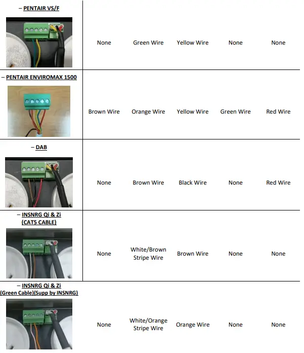
If the pump installed is one of the following, Reltech, Reltech P 485, Theraflo TVS, Theralux TVS Pro 1, Theralux TVS Pro 2, Hayward 485, Hayward P 485, Speck, Henden, Insnrg Qi, Insnrg Zi, Sunlover Oasis V Series, or a Davey ProMaster VSD 400, a comms cable needs to be purchased separately.
If the pump installed is a Waterco ECO-V, Pentair IntelliFlo, Pentair EnviroMax 1500, Hayward TriStar, Hayward MaxFlo VS, Pentair EnviroMax 800, or a DAB VS pump, the pump communication cable needs to be purchased through the respective manufacturers or distributors.
- If the filtration pump is a single speed pump, plug it directly into one of the power sockets located on either the Master Controller or on an Expansion Unit.
The pump may be plugged into the Sanitiser pump outlet and the Sanitiser plugged into the controller power outlet. In Appliances you would set this outlet to be the Filter Pump.
Note: In this situation, whenever the pump is turned on the Sanitiser will also be turned on. This will mean that during the course of other features being run, (ie heating, water features, etc) extra sanitisation (above what is set in the filter cycle/s) will occur, possibly leading to over chlorination.
- Plug all other appliance power cables that will be controlled by the POOLTEK into the power sockets located beneath the Controller and/or the Expansion Unit/s, ensuring that maximum current loads are not exceeded.
Max Current Loads are as follows:
- Master Controller (2 power outlets) 9.9 Amps / 2370 Watts,
- 10Amp Expansion Unit (3 power outlets) 9.9 Amps / 2370 Watts
- 15Amp Expansion Units (2 or 3 power outlets) 14.9 Amps / 3570 Watts
- 10 & 15Amp Heater Expansion Units (2 or 3 power outlets) Max Current Loads as per above for respective units.
Note: Any appliance can be plugged into any output socket in either the Master controller or any Expansion Unit, so long as the above Maximum Current Loads are not exceeded.
CONNECTION TO WATERCO ECO-V VARIABLE SPEED PUMPS

- WATERCO ECO-V VARIABLE SPEED PUMPS MAY BE CONTROLLED VIA THE POOLTEK SPEED CONTROL FUNCTION BY INSERTING THE CONTROL CABLE WIRES INTO THE PUMP CONTROL TERMINAL BLOCK. THE WATERCO PUMP CONTROL CABLE SHOULD BE
- USED AND THE PLUG SOCKET REMOVED TO ALLOW WIRE TERMINATION INTOTHE FIVE WAY SCREW TERMINAL AS PER THE ABOVE PICTURE.
- COLOUR ORDER FROM LEFT TO RIGHT IS BLUE, BLACK, WHITE, GREEN, RED.
- WHEN SETTING UP VIA THE APP SELECT WATERCO HYDROSTORM ECO AS THE PUMP TYPE.
5 PIN PUMP CONNECTION PLUG

Pump Priming & Connection
Reltech P (485) / Oasis V Series / Theralux TVS Pro 2/Insnrg Zi
- Turning Off Priming
- Quickly press the ‘stop’ button three times.
- The display will show ‘P Of’ when priming is turned off.
- Turning On 485 Communication
- Hold the ‘stop’ button for 10 secs.
- The display will show e.g. ‘P 5’ (to select priming time in minutes). Press ‘set’ button to move to next.
- The display will show e.g. ‘2400’ (to select priming speed in RPM). Press ‘set’ button to move to next.
- The display will show ‘Rb Of’. Press Up or Down button to change to ‘Rb On’. Press ‘set’ button to confirm.
- When communication with Pooltek is successful, the display will show ‘- – – -‘
Pentair enviroMAX 1500
- Turning Off Priming
- Press the ‘Start / Stop’ button to start the pump.
- The display will alternate between ‘Pri’ and ‘2800’ and ’04:59’ to show priming at 2800 RPM for 5mins.
- Press the ‘–‘ to turn the priming speed down; when it reaches below 1700, priming is turned off.
- The display will then alternate between ‘Pri’ and ‘Off’.
Note: External control must be off.
- Turning On External Control
- Stop the pump by pressing the ‘Start / Stop’ button.
- Hold the ‘Start / Stop’ button for ~5 seconds.
- The light next to ‘Ext. Control Only’ will be lit green.
- Press the ‘Start / Stop’ button.
- The light next to ‘Start / Stop’ will be lit green.
Pentair VS/F
- Turning Off Priming
- Disconnect the RS-485 communication cable from the pump.
- On the pump control module, press Menu and use the Arrow buttons to scroll and select “Priming”.
- Use the Arrow buttons to select “Disabled”, then press the Back button to exit the menu.
- Re-install the communication cable to the pump.
- Turning On External Control
- Press the Menu button, use the Up or Down arrow to scroll to Ext Ctrl and press Select.
- “Program 1” will be displayed and press Select to enter.
- “Operation Mode” will be displayed, press Select and use the Up or Down buttons to choose between“Enabled” or “Pump Off”, press Save. Note: the program must be enabled to proceed further into themenu.
- Use the Up or Down arrow to scroll to “Set Type” and press Select.
- Use the Up or Down arrow to choose between “Speed” or “Flow” settings and press Save.
- Use the Up or Down arrow to scroll to “Set Speed/Flow” (depending on what was chosen in the previousstep), press Select and then use the Up & Down arrows to adjust the speed/flow settings to what isrequired & press Save.
- There is no need to set a “Stop Delay” so press the Save button to save your settings and then press Back.This will allow you to set “Program 2”.
- Use the Up or Down arrow to scroll to “Program 2” and repeat steps b) to g) for programs 2 to 4.
Hayward 485 / Theralux 485
Note: Theralux pump will be supplied with 485 communication already enabled. If it isn’t, follow the steps below.
- Turning Off Priming
- Priming is automatically taken off when the below connection process (4.2) is done.
- Turning On 485 Communication
- Hold stop, press speed 2 to show “LOW”.
- Press speed 1 until the screen shows “IO”.
- Press speed 2 to show “485”.
- Press stop to save settings.
Once there is control over the pump, the pump will show “NBUS”.
Insnrg Qi
- Turning Off Priming
- Press Enter, scroll to Priming.
- Set Minutes to 0
- Turning On External Control
- Connect the pump control cable between the pump and the Pooltek controller and control is automatically instated.
Waterco / Reltech/Theralux/Henden (with Fasco Motor)
- Turning Off Priming
- Disconnect the pump communication cable from the pump
- Press and hold the Stop button for 10 seconds to remove the priming function.
- If required, adjust pump speeds (as per manufacturer’s instructions) to suit then save prior to reconnecting the communication cable.
DAB E.Swim
- Turning Off Priming
- Scroll to select the Settings Wheel (
 )Press Enter.
 - Scroll to Priming and press Enter.
- Change Enable to NO.
- Scroll to select the Settings Wheel (
- Turning On External Control
- Scroll to select the Settings Wheel (). Press Enter.
- Scroll to External Control and press Enter.
- Scroll to Settings and press Enter.
- Change config to ENABLE.
- Change source speed to 4-20mA.
- If pump displays ‘System Disabled’, press the Run/Stop button.
- Scroll to select the Settings Wheel (
Davey ProMaster VSD 400
Note: A Cat6 (568A) cable is required to connect the pump to the Aqutek. Cut one end off and wire as per page 4.
- Turning On External Control
- Set the pump Dial to Bluetooth position – the LED will turn on white and then blue.
- When the Pooltek is controlling the pump, the LED will flash green.
Hayward MaxFlo VS / Hayward TriStar VS
- Configuring the pump
- Press the ‘Run/Stop’ button to halt the pump.
- Press and hold the ‘Disp/Func’ until the display shows ‘Confg’.
- The display will then show e.g ‘Pr0.03’ which stands for ‘Prime for 3 minutes’.
- Keep pressing the ‘Disp/Func’ button until the display shows ‘485 n’. Press the ▾ button to set it to ‘y’.
- The display will show ‘r5485’ and then ‘Stop’.
- Communication between Pooltek & pump
- Press the ‘Run/Stop’ button; if the display alternates between ‘r5485’ and ‘FAIL’ check the connection of the pump communication cable.
- Connect the pump to the Pooltek as per the cable connection diagram above; the pump display will show ‘□ 0’ when communication with the Pooltek starts.
- The value 0 will change according to the speed set by the Pooltek and the display will alternate between this RPM value and the power value e.g. ‘□ 600’ and ‘P 14’ for RPM=600 and Power=14W.
Note:
- The pump will display ‘r5485’ and ‘FAIL’ until the Pooltek sends it a command to turn on.
If there is no reason for the pump to be running, the ‘FAIL’ message may remain until the Pooltek sends the command to turn on the pump.
Speck (with Fasco Motor)
- Turning Off Priming
- Disconnect the pump communication cable from the pump
- Turn the pump OFF (Display shows ‘OFF’)
- Press and hold the ‘Set’ button for 3 seconds until the speed is displayed.
- Press the ‘OK’ button until the time is displayed.
- Press the ↓ button until the value is ‘00’.
- Press the ‘OK’ button to confirm and save.
- If required, adjust pump speeds (as per manufacturer’s instructions) to suit then save prior to reconnecting the communication cable.
SETUP
This sequence must be followed:
- Turn the controller on at the power, wait for 10 seconds before turning the power on to the first Expansion Unit, wait a further 10 seconds before turning the power on to the second Expansion Unit (if fitted).
Note: This sequence is to ensure that the Master Controller recognises the Expansion Units in the correct order. Do this within the first 2mins while the Master Controller is actively scanning. The Wi-Fi Indicator should be slowly FLASHING.
When you first start the Pooltek controller, you will be prompted to connect the controller to the Wifi network.
- You have the option to continue with connecting the controller to Wifi (Yes) or connect it at a later stage (No). Use the ↑ or ↓ arrow buttons to select your preferred option, and press Enter.
- If you selected Yes to continue with the connection process, it will ask you if you would like to connect the controller using either the App or to connect it Manually.
- If you select APP (2.4Ghz only), follow steps 5 – 8 on page 9 of this manual.
Note: You will need to ensure that the modem (that the Pooltek controller is being connected too), is only running on 2.4Ghz band width only. - If you select Manual, the controller will automatically start searching for nearby Wifi networks.
- Use the↑ or ↓ buttons to scroll through the Wifi networks found, press Enter on the appropriate network. See Step 12 on page 10 of this manual for the process to input the password.
Note: Manual is the best option if you are connecting to a Dual Band network (ie; 2.4Ghz + 5Ghz).
Once the Wifi connection is completed (or if you selected No to connecting the controller to Wifi), you will be asked if any Expansion Units are being connected. If not say No and the controller will go to normal functionality and be ready for programming. - If you select Yes, the controller will automatically take you too 6-10 Expansion Units, press Enter.
Note: You are looking to ensure that the Master Controller has recognised that there are Expansion boxes connected. - The Controller will display: EXP: 1 V1.00B03
- EXP: 2 V1.00B03 (if 2 expansion units are installed)
EXP: 1/2 V1.01H (if a Heater Expansion unit is installed)
- EXP: 2 V1.00B03 (if 2 expansion units are installed)
- Press Enter, controller will display NUMBER EXP UNITS: use the ↑ or ↓ buttons to alter number of Expansion Units required: 0, 1, or 2. Once the amount required is displayed, press Enter to accept.
- The controller will then display RESET ALL ADDRESS………NO, press Enter to continue through to connecting an Aquachem controller or press the Menu button to return to normal operation to continue programming the system through your App.
Note: If the controller displayed NONE for EXP: 1 & 2, then you will need to use the ↑ or ↓ buttons to change the NO to a YES for Reset All Address, when the controller displays DONE, press Enter. The controller will then display Search For Exp Units, (make sure that the power to the second unit is turned off), then use the ↑ or ↓ buttons to change the NO to a YES, press Enter. When Exp Unit 1 is found, turn the power on to the second unit. When found, press the Menu button to return to normal operation.
The controller is now ready to be set up using the App.
Note: Wifi connection description available on pages 9 & 10 of this manual if you have an issue connecting.
App Based Wifi Connection
Controllers with software version V1.16B01 and newer, can use the following connection method:
- ownload the Pooltek App
- Scan the QR code on the front of this booklet or rear of main controller

Follow guided steps in app to successfully connect Wi-Fi
Controllers with software version V1.15 and older, are to use the following connection method:
- Scan the QR code for the system if you haven’t already done so. The QR code is located on the back of the Master Controller. Return to the Main Menu in the App.
You can go into the App menu, go to Device, tap on QR “Scan” to bring up the QR code scanning window. - Make sure the Wi-Fi network (ie: Modem) the Pooltek will be connected to is turned on and setup to run on the 2.4Ghz frequency band. If it is, then use the Smartphone Connection process (as per the below) or if not then utilise the Dual Band setup on the next page.
- Turn the controller on at the power point, wait for 10 seconds before turning the power on to the first Expansion Unit. Wait a further 10 seconds before turning on the second Expansion Unit, if fitted.
When the controller is turned on, an arrow should be blinking in the lower right-hand corner of the controller’s LCD screen (above Wi-Fi on the label). If the arrow isn’t blinking, turn the Master Controller OFF for 5 seconds, then back on again.
Connecting your Pooltek to Wi-Fi Smartphone Connection - With the Pooltek controller powered on, open the menu in the App. Tap on the menu option Device. This will open another menu screen, tap on Wi-Fi Connection ‘Setup’.
- With the Pooltek controller powered on, open the menu in the App. Tap on the menu option Device. This will open another menu screen, tap on Wi-Fi Connection ‘Setup’.
- When you enter Wi-Fi Connection ‘Setup’, the customers Wi-Fi network name should be displayed. You will need to enter their password on the line below then press either proceed or confirm. Note: Needs to be done while the Wi-Fi arrow is blinking.
- The App should display that the ‘Device is Connected’. Once connected, click on the Device option, then Device Information. In this screen the App will display if there is a software update (for the controller) to be downloaded. If there is, go ahead and update the system. The controller will re-start itself when the update is complete. From here you can go back to the main menu of the App. You will then be able to setup the system through the App.
- Start in the menu option ‘Appliance Setup’ and work down through the menu options (Pump Setup, Light Setup, Heating Setup, Spa Setup and Misc) before returning to setup Filtration Times, Temperature, and Timers.
NOTE
- If you notice that the App and or controller is slow to react or you are losing connection to the controller, check the Wifi signal strength (as described in App Features) as you may benefit from a Wi-Fi extender being installed.
When completed the App will display all settings currently set in your controller. You can select or alter any of the settings that are currently active in your Master Controller.
Controller Based Wifi Connection (For Dual Band Networks)
NEW CONNNECTION
This method is done through the controller itself, when the controller has never been connected to a Wifi network previously.
- If the controller has previously been connected to a Wifi network and you are trying to connect the controller to an extender/or a different Wifi network, then follow the “Previously Connected” process further down the page.
- Press the “Menu” button until the controller displays “1. Filter Times”.
- Use the ↑ or ↓ arrows to locate “6. Installer Menu”. Press “Enter”.
- The controller will display “6-1 Appliances”.
- Use the ↑ or ↓ arrows to locate “6-12 Wi-Fi”. Press “Enter”.
- The controller will display “Wi-Fi On Off”.
- Ensure “On” is blinking. Press “Enter”.
- If “Off” is blinking, use the ↑ or ↓ arrows to change before pressing “Enter”.
- The controller will display “Wi-Fi Network”. Press “Enter”.
- The controller will display “Search Wi-Fi Network Yes No”.
- Use the ↑ or ↓ arrows to ensure that “Yes” is blinking. Press Enter.
- The controller will briefly display “Searching for Wi-Fi Network” before displaying local Wi-Fi networks & strength of the network.
- 80 to -90dBm signals a weak connection.
- 60 to -80dBm signals a moderate connection.
- 60 + signals a stable connection.
- Use the ↑ or ↓ arrows to find the network you would like to connect to & press “Enter”.
- Enter the password to the network & press “Enter”. Use the following instructions to enter the password manually.
- Press “Spa” to choose between lowercase/uppercase letters, numerals or symbols.
- Use the ↑ or ↓ arrows to cycle through characters.
- After 3 seconds of resting on an option, the cursor will move across and you will be able to cycle through to the next character.
- Press “Back” to remove the last character if you make a mistake.
- Press “Enter” to confirm password once all characters have been selected.
- The controller will then display “Connecting to Wifi”, and “Connected to Wifi” when completed.
PREVIOUSLY CONNECTED
- Follow steps 1-8 as per the above instructions.
- Instead of entering “Yes” for “Search Wifi Network” you will Press Enter on “No”.
- The controller will display “Reset Wifi Settings No”
- Use the ↑ or ↓ arrows to ensure that “Yes” is blinking. Press Enter.
- The controller will display “Wifi Settings Reset OK”. Press Enter.
- The controller will display “Restart Controller Yes/No”.
- Use the ↑ or ↓ arrows to ensure that “Yes” is blinking. Press Enter.
- The controller will restart itself and revert to displaying normal running processes.
- Follow the steps 1-12 as per the above instructions for a controller that has never been connected to a Wifi Network.
Controller will say that it is connected to Wifi and then you will be able to utilise the App to set up the system.
POOLTEK ADDITIONS
Pooltek Chemical Doser

The Pooltek Chemical Doser is designed to monitor and automatically adjust the pH and Chlorine (ORP) levels of all types of Pools & Spas while the filtration pump is running.
Once the pH and ORP levels have been set in the Pooltek App, the Pooltek Doser will automatically dose Pool acid (when it is required) to maintain the set pH level. The Pooltek Doser will also maintain the systems ORP by turning the Chlorinator On or Off to maintain the selected ORP level.
The Pooltek Doser can be used as a pH only system or an ORP probe can be added to your system.
DUAL HEATER INTERFACE KITS

The Kit 13, 14, 15, & 16 Dual Heater Interface kits are designed to be connected to the Pooltek unit and switch between or switch on 2 heating sources (Gas Heater & Heat Pump).
- Kit 13 – Heat Pump on Pool & Gas Heater on Spa with gas heater override to heat the pool.
- Kit 14 – Heat Pump on Pool & Spa, Gas Heater on Spa with override for the pool.
- Kit 15 – Dual heat sources for Pool & Spa, both heaters switched on at the same time for both uses.
- Kit 16 – Dual heat sources for a Pool only or Spa only, both heaters switched on at the same time.
Both heat sources must be in the Filtration line.
WARRANTY
- This range of product is covered by a limited 3 year warranty against component failure or faulty workmanship from the date of installation.
- Faulty units should be returned in the first instance to the dealer from which the unit was purchased.(Return to Base)
- Damage to the unit due to misuse, power surges, corrosion from pool chemical fumes, lightning strikes and or installation that is not in accordance with the manufacturer’s instruction may void the warranty.
- Warranty does not include on-site labour or travel costs to or from installation site.
- Valves and actuators are covered by a 12 month warranty at the discretion of their manufacturer.
If the power cord is damaged, do not use the controller. Return the unit to the supplier for repair.
CUSTOMER RECORD (To be retained by the customer)
DEALER/INSTALLER NAME
SERIAL NUMBER
DATE INSTALLED
OFFICES – AUSTRALIA
NSW – Sydney (Head Office)
Tel: +61 2 9898 8600
QLD – Brisbane
Tel: +61 7 3299 9900
VIC/TAS – Melbourne
Tel: +61 3 9764 1211
WA – Perth
Tel: +61 8 9273 1900
SA/NT – Adelaide
Tel: +61 8 8244 6000
Dontek Electronics Pty Ltd
PO Box 239, Bayswater VIC 3153 Australia
Phone: +613 9762 8800 Email: sales@dontek.com.au
POOLTEK – Quick Start Guide 1.5.2 updated2 – May 2025
FAQ
Q: Can any appliance be plugged into any output socket?
A: Yes, any appliance can be plugged into any output socket in either the Master controller or Expansion Unit, ensuring the maximum current loads are not exceeded.
Documents / Resources
 |
Waterco AQUASMART 5 Pooltek Pool Automation [pdf] Installation Guide AQUASMART 5, AQUASMART 5 Pooltek Pool Automation, Pooltek Pool Automation, Pool Automation, Automation |