User Manual
![]()
VLVWIP2000-ENC
VLVWIP2000-DEC
JPEG2000 AVoIP Encoder and Decoder

All Rights Reserved
Version: VLVWIP2000-ENC_2025V1.0
Version: VLVWIP2000-DEC_2025V1.0
![]()
JPEG2000 AVoIP Encoder and Decoder
Preface
Read this user manual carefully before using the product. Pictures shown in this manual are for reference only. Different models and specifications are subject to real product.
This manual is only for operation instruction, please contact the local distributor for maintenance assistance. In the constant effort to improve the product, we reserve the right to make functions or parameters changes without notice or obligation. Please refer to the dealers for the latest details.
FCC Statement
This equipment generates, uses and can radiate radio frequency energy and, if not installed and used in accordance with the instructions, may cause harmful interference to radio communications. It has been tested and found to comply with the limits for a Class B digital device, pursuant to part 15 of the FCC Rules. These limits are designed to provide reasonable protection against harmful interference in a commercial installation.
Operation of this equipment in a residential area is likely to cause interference, in which case the user at their own expense will be required to take whatever measures may be necessary to correct the interference.
Any changes or modifications not expressly approved by the manufacture would void the user’s authority to operate the equipment.
![]()

![]()
![]()
SAFETY PRECAUTIONS
To ensure the best performance from the product, please read all instructions carefully before using the device. Save this manual for further reference.
- Unpack the equipment carefully and save the original box and packing material for possible future shipment.
- Follow basic safety precautions to reduce the risk of fire, electrical shock and injury to persons.
- Do not dismantle the housing or modify the module. It may result in electrical shock or burn.
- Using supplies or parts not meeting the products’ specifications may cause damage, deterioration or malfunction.
- Refer all servicing to qualified service personnel.
- To prevent fire or shock hazard, do not expose the unit to rain, moisture or install this product near water.
- Do not put any heavy items on the extension cable in case of extrusion.
- Do not remove the housing of the device as opening or removing housing may expose you to dangerous voltage or other hazards.
- Install the device in a place with fine ventilation to avoid damage caused by overheat.
- Keep the module away from liquids.
- Spillage into the housing may result in fire, electrical shock, or equipment damage. If an object or liquid falls or spills on to the housing, unplug the module immediately.
- Do not twist or pull by force ends of the optical cable. It can cause malfunction.
- Do not use liquid or aerosol cleaners to clean this unit. Always unplug the power to the device before cleaning.
- Unplug the power cord when left unused for a long period of time.
- Information on disposal for scrapped devices: do not burn or mix with general household waste, please treat them as normal electrical wastes.
Thank you for purchasing this product
For optimum performance and safety, please read these instructions carefully before connecting, operating or adjusting this product. Please keep this manual for future reference.
Surge protection device recommended
This product contains sensitive electrical components that may be damaged by electrical spikes, surges, electric shock, lighting strikes, etc. Use of surge protection systems is highly recommended in order to protect and extend the life of your equipment.
1. Introduction
This product is based on JPEG2000 technology. It integrates Copper port and Fiber port within a single box. Encoder input supports up to 4K60 4:4:4, audio embedding or extracting. Decoder output supports up to 4K60 4:4:4, audio extracting. The product supports ARC/eARC/S/PDIF/Analog audio return function, also supports USB2.0/KVM/Camera, 1G Ethernet, bidirectional RS-232, two-way IR and POE function. Guest mode controls of RS-232, IR, CEC are supported. Built-in two channel RELAY ports and two channel I/O ports for contact control. Dante AV-A mode is supported if the product is license activated.
Built-in MJPEG Substream which supports plenty API commands to achieve flexible configurations is useful for 3rd party control Apps to preview video content.
The system is based on Linux for software development, provides flexible control methods, that are based on the intelligent networking of 1G Ethernet Switch.
2. Features
☆ HDCP 2.2 compliant
☆ Support 18Gbps video bandwidth
☆ Input and output video resolution is up to 4K60 4:4:4, as specified in HDMI 2.0b
☆ Signal transmission distance can be extended up to 328ft / 100m via CAT5E/6/6A/7 cable
☆ Transmit video, analog/digital audio, IR , RS-232, CEC and USB over Ethernet
☆ Integrate Copper port and Fiber port within a single box
☆ ARC/eARC/S/PDIF/Analog audio return function
☆ Dante AV-A mode is supported if license activated
☆ Channel configuration via front panel buttons and LED screen
☆ Built-in two channel RELAY ports and two channel I/O ports for contact control
☆ Support unicast and multicast functions
☆ Support point-to-point, video matrix and video wall functions (video wall supports up to 9×9)
☆ Intelligent video wall class management
☆ Support MJPEG Substream real-time preview
☆ 1G Ethernet Switch
☆ Support POE function
☆ Built-in web page configuration and control, Telnet and SSH as well
☆ HDMI audio formats: LPCM 2.0/5.1/7.1CH, Dolby Digital/Plus/EX, Dolby True HD, DTS, DTS-96/24, DTS-EX DSD, DTS High Res, DTS-HD Master
☆ Smart networking design for easy and flexible installation
3. Package Contents
| Qty | Item |
| 1 | 4K60 over IP 1GbE Encoder |
| 1 | IR Receiver cable (1.5 meters) |
| 1 | IR Blaster cable (1.5 meters) |
| 3 | 3-pin 3.81mm Phoenix connector |
| 2 | 4-pin 3.81mm Phoenix connector |
| 1 | 12V/2.5A Locking Power adapter |
| 2 | Mounting ear |
| 4 | Machine screw (KM3*4) |
| 1 | User Manual |
or
| Qty | Item |
| 1 | 4K60 over IP 1GbE Decoder |
| 1 | IR Receiver cable (1.5 meters) |
| 1 | IR Blaster cable (1.5 meters) |
| 3 | 3-pin 3.81mm Phoenix connector |
| 2 | 4-pin 3.81mm Phoenix connector |
| 1 | 12V/2.5A Locking Power adapter |
| 2 | Mounting ear |
| 4 | Machine screw (KM3*4) |
| 1 | User Manual |
4. Specifications
Technical
| HDMI Compliant | HDMI 2.0b |
| HDCP Compliant | HDCP 2.2 |
| Video Bandwidth | 18Gbps |
| Video Compression Standard | JPEG2000 |
| Video Network Bandwidth | 1G |
| Video Resolution | Up to 4K@60Hz 4:4:4 |
| Color Depth | Input: 8/10/12-bit Output: 8-bit |
| Color Space | RGB 4:4:4, YCbCr 4:4:4 / 4:2:2 / 4:2:0 |
| HDMI Audio Formats | LPCM 2.0/5.1/7.1CH, Dolby Digital/Plus/EX, Dolby True HD, DTS, DTS-96/24, DTS-EX DSD, DTS High Res, DTS-HD Master |
| Transmission Distance | 100M CAT5E/6/6A/7 |
| IR Level | Default 12V, optional 5V |
| IR Frequency | Wideband 20K – 60KHz |
| ESD Protection | IEC 61000-4-2: ±8kV (Air-gap discharge) & ±4kV (Contact discharge) |
Connection
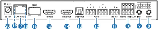
| Encoder | Input: 1 x HDMI IN [Type A, 19-pin female] 1 x L/R AUDIO IN [3-pin 3.81mm Phoenix connector] Output: 1 x HDMI OUT [Type A, 19-pin female] 1 x L/R AUDIO OUT [3-pin 3.81mm Phoenix connector] 1 x SPDIF OUT [Optical audio connector] Control: 1 x RS-232 [3-pin 3.81mm Phoenix connector] 1 x LAN (POE) [RJ45 jack] 1 x FIBER [Optical fiber slot] 1 x USB 2.0 HOST [Type B, 4-pin female] 2 x USB 2.0 DEVICE [Type-A, 4pin female] 2 x RELAYS [3.81mm Phoenix connector] 2 x DIGITAL IO [3.81mm Phoenix connector] 1 x IR IN [3.5mm Audio Jack] 1 x IR OUT [3.5mm Audio Jack] |
| Decoder | Input: 1 x SPDIF IN [Optical audio connector] 1 x L/R AUDIO IN [3-pin 3.81mm Phoenix connector] Output: 1 x HDMI OUT [Type A, 19-pin female] 1 x L/R AUDIO OUT [3-pin 3.81mm Phoenix connector] Control: 1 x RS-232 [3.81mm Phoenix connector] 1 x LAN (POE) [RJ45 jack] 1 x FIBER [Optical fiber slot] 2 x USB 1.1 DEVICE [Type-A, 4-pin female] 2 x USB 2.0 DEVICE [Type-A, 4-pin female] 2 x RELAYS [3.81mm Phoenix connector] 2 x DIGITAL IO [3.81mm Phoenix connector] 1 x IR IN [3.5mm Audio Jack] 1 x IR OUT [3.5mm Audio Jack] |
Mechanical
| Housing | Metal enclosure |
| Color | Black |
| Dimensions | Encoder/Decoder: 204mm [W] x 136mm [D] x 25.5mm [H] |
| Weight | Encoder: 631g, Decoder: 626g |
| Power Supply | Input: AC100 – 240V 50/60Hz, Output: DC 12V/2.5A (US/EU standards, CE/FCC/UL certified) |
| Power Consumption | Encoder: 8.52W, Decoder: 7.08W (Max.) |
| Operating Temperature | 32 – 104°F / 0 – 40°C |
| Storage Temperature | -4 – 140°F / -20 – 60°C |
| Relative Humidity | 20 – 90% RH (no condensing) |
| Resolution / Cable Length | 4K60 – Feet / Meters | 4K30 – Feet / Meters | 1080P60 – Feet / Meters |
| HDMI IN / OUT | 16ft / 5M | 32ft / 10M | 50ft / 15M |
| The use of “Premium High Speed HDMI” cable is highly recommended. | |||
5. Operation Controls and Functions
5.1 Encoder Panel
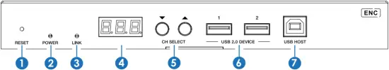
| No. | Name | Function Description |
| 1 | RESET | After powering on the device, press and hold the RESET button until the POWER LED and LINK LED flash at the same time, release the button to reset the device to factory settings. |
| 2 | POWER LED (Red) |
|
| 3 | LINK LED (Green) | Connection status LED.
|
| 4 | LED screen | Shows Encoder ID as default. Displays the corresponding options of configuration functions during setting Encoder configurations. |
| 5 | CH SELECT | Used to set Encoder ID and other settings. |
| 6 | USB 2.0 DEVICE | Connect to USB 2.0 devices. |
| 7 | USB HOST | USB-B connector for connecting a PC. |
| 8 | IR OUT | IR signal output port. The IR level can be set to 5V or 12V (default) through the panel buttons. |
| 9 | IR IN | IR signal input port. The IR level can be set to 5V or 12V (default) through the panel buttons. |
| 10 | RELAYS I DIGITAL IO | VCC: Power output (12V or 5V configurable), maximum to 12V @50mA, 5V@ 100mA loading. The default output is 12V. RELAYS: 2 channel low-voltage relay ports, each group is independent and isolated, maximum to 1A 30VDC loading. Contacts are disconnected by default. DIGITAL IO: 2 channel GPIO ports, for digital level signal output control or input detection (up to 12V level detection). The output control mode (default mode, low level as default output) or input detection mode is configurable. The DIGITAL IO internal pull-up voltage follows the VCC. Output control mode: a. The maximum withstand sink current is 50mA when outputting low level. b. When VCC is 5V and high level is output, the maximum current driving capacity is 2mA. c. When VCC is 12V and high level is output, the maximum current driving capacity is 5mA. Input detection mode: a. When VCC is 5V, DIGITAL IO is pulled up to 5V internally through a 2.2K ohm resistor. b. When VCC is 12V, DIGITAL IO is pulled up to 12V internally through a 2.2K ohm resistor. |
| 11 | RS-232 | RS-232 serial port, supporting RS-232 command pass-through and local serial port control. |
| 12 | AUDIO IN/OUT | AUDIO IN: Analog audio input port, the audio can be embedded into the HDMI signal for pass-through over to HDMI output and audio out on Decoder, or be loop out by the AUDIO OUT port on Encoder. |
| AUDIO OUT: Analog audio output port. It can output the audio extracted from the HDMI IN port (in case of LPCM) . Also it can output the audio transmitted from the AUDIO IN port of the Decoder in unicast mode (point-to-point direct connection). | ||
| 13 | SPDIF OUT | S/PDIF signal output port. It can output the ARC or S/PDIF audio returned from the Decoder when both the Encoder and Decoder are correspondingly set to the ARC or S/PDIF audio return mode (Set through the Controller Box or API commands in Multicast mode; Set through the front panel buttons in unicast mode). |
| 14 | HDMI OUT | HDMI local loop output port, connected to an HDMI display device such as TV or monitor. |
| 15 | HDMI IN | HDMI signal input port, connected to an HDMI source device such as Blu-ray Player or Set-top box with an HDMI cable. |
| 16 | FIBER | Connect with optical fiber module, and transmit signals to the Decoder with an optical fiber cable directly or through a Switch. |
| 17 | LAN (POE) | 1G LAN port, connect network Switch to form a distributed system. Note: When network switch delivers POE power supply, DC 12V adapter doesn’t need to apply on the unit. |
| 18 | Data Signal Indicator lamp (Yellow) | Light flashing: There is data transmission. ▪ Light off: There is no data transmission. |
| 19 | Link Signal Indicator lamp (Green) | Light on: The network cable is connected normally. ▪ Light off: The network cable is not connected well. |
| 20 | DC 12V | The device can be powered via two methods:
When the Switch supports POE function, DC power supply is not needed. |
Operation description of the LED screen and CH SELECT buttons (For Encoder).
1, ENC ID: After the system is powered on, the Encoder’s LED screen will show the ENC ID (000 by default if not set).
2, IP address: Press and hold the UP button for 5 seconds, the Encoder’s LED screen will show in sequence “IPx”, “xxx”, “xxx”, “xxx”, “xxx”, which are the IP mode and IP address of Encoder.
3, Configuration mode: Press and hold UP + DOWN buttons at the same time for 5 seconds, then release to enter the configuration mode with “CFN” displaying on the LED screen.
4, Device ID settings: After entering the configuration mode, press the UP/DOWN button to enter the first page with the current ID number (e.g. 001) displaying on the LED screen (000 by default). Press and hold UP + DOWN buttons for 5 seconds, then release to enter the ID settings mode, in which the ID number (e.g. 001) on the LED screen will flash at 1Hz, then press the UP/DOWN button to select the device ID you desired (ID range: 000~762), then press and hold UP + DOWN buttons for 5 seconds to confirm the setting and stop flashing. After setting, the unit will reboot automatically.
Note: The device ID can not be modified in Controller Box mode.
5, EDID settings: After entering the configuration mode, press the UP/DOWN button to enter the second page with “E00” (in which “E” refers to EDID, “00” to EDID ID) or “COP” (which indicates copy EDID) displaying on the LED screen (E15 by default).
Press and hold UP + DOWN buttons for 5 seconds, then release to enter the EDID settings mode, in which the EDID ID number (e.g. E01) on the LED screen will flash at 1Hz, then press the UP/DOWN button to select the EDID ID you desired, then press and hold UP + DOWN buttons for 5 seconds to confirm the setting and stop flashing.
The corresponding EDID ID is as follows:
| EDID ID | EDID Description |
| E00 | 1080P_Stereo_Audio_2.0_SDR |
| E01 | 1080P_DolbyDTS_5.1_SDR |
| E02 | 1080P_HD_Audio_7.1_SDR |
| E03 | 1080I_Stereo_Audio_2.0_SDR |
| E04 | 1080I_DolbyDTS_5.1_SDR |
| E05 | 1080I_HD_Audio_7.1_SDR |
| E06 | 3D_Stereo_Audio_2.0_SDR |
| E07 | 3D_DolbyDTS_5.1_SDR |
| E08 | 3D_HD_Audio_7.1_SDR |
| E09 | 4K2K30_444_Stereo_Audio_2.0_SDR |
| E10 | 4K2K30_444_DolbyDTS_5.1_SDR |
| E11 | 4K2K30_444_HD_Audio_7.1_SDR |
| E12 | 4K2K60_420_Stereo_Audio_2.0_SDR |
| E13 | 4K2K60_420_DolbyDTS_5.1_SDR |
| E14 | 4K2K60_420_HD_Audio_7.1_SDR |
| E15 | 4K2K60_444_Stereo_Audio_2.0_SDR |
| E16 | 4K2K60_444_DolbyDTS_5.1_SDR |
| E17 | 4K2K60_444_HD_Audio_7.1_SDR |
| E18 | 4K2K60_444_Stereo_Audio_2.0_HDR_10-bit |
| E19 | 4K2K60_444_DolbyDTS_5.1_HDR_10-bit |
| E20 | 4K2K60_444_HD_Audio_7.1_HDR_10-bit |
| E21 | DVI_1280x1024 |
| E22 | DVI_1920x1080 |
| E23 | DVI_1920x1200 |
Note: In point to point connection mode, before using the EDID copy function, all codecs need to be set to CA1 unicast mode, and after setting, the HDMI cable of the Decoder needs to be re-plugged to report the EDID of TV to the Encoder.
6, IR mode settings: After entering the configuration mode, press the UP/DOWN button to enter the third page with “IR2” (in which “IR” refers to IR and “2” to 12V) displaying on the LED screen (IR2 by default). Press and hold UP + DOWN buttons for 5 seconds, then release to enter the settings mode, in which the IR mode (IR1 or IR2) on the LED screen will flash at 1Hz, then press the UP/DOWN button to select the IR mode, then press and hold UP + DOWN buttons for 5 seconds to confirm the setting and stop flashing.
The corresponding IR mode options are as follows:
IR1: 5V IR wire
IR2: 12V IR wire
7, Audio embedding mode settings: After entering the configuration mode, press the UP/DOWN button to enter the fourth page with “HDI/ANA” displaying on the LED screen (HDI by default). Press and hold UP + DOWN buttons for 5 seconds, then release to enter the settings mode, in which the audio return mode (HDI/ANA) on the LED screen will flash at 1Hz, then press the UP/DOWN button to select the mode, then press and hold UP + DOWN buttons for 5 seconds to confirm the setting and stop flashing.
The corresponding audio embedding mode options are as follows:
HDI: HDMI audio embedding
ANA: Analog audio embedding
8, IP mode settings: After entering the configuration mode, press the UP/DOWN button to enter the fifth page with “IP1/IP2/IP3” displaying on the LED screen (IP3 by default).
Press and hold UP + DOWN buttons for 5 seconds, then release to enter the settings mode, in which the IP mode (IP1/IP2/IP3) on the LED screen will flash at 1Hz, then press the UP/DOWN button to select the mode, then press and hold UP + DOWN buttons for 5 seconds to confirm the setting and stop flashing. After setting, the unit will reboot automatically.
The corresponding IP mode options are as follows:
IP1: Static IP mode (Default IP address: 169.254.100.254)
IP2: DHCP IP mode
IP3: Auto IP mode (Default assigned network segment: 169.254.xxx.xxx)
Note: The IP mode can not be modified in Controller Box mode.
9, Fiber/Copper mode settings: After entering the configuration mode, press the UP/DOWN button to enter the sixth page with “CPP/FIB” displaying on the LED screen (CPP by default). Press and hold UP + DOWN buttons for 5 seconds, then release to enter the settings mode, in which the Fiber/Copper mode (CPP/FIB) on the LED screen will flash at 1Hz, then press the UP/DOWN button to select the mode, then press and hold UP + DOWN buttons for 5 seconds to confirm the setting and stop flashing. After setting, the unit will reboot automatically.
The corresponding Fiber/Copper mode options are as follows:
CPP: Copper mode
FIB: Fiber mode
10, Multicast mode settings: After entering the configuration mode, press the UP/DOWN button to enter the seventh page with “CA1/CA2” displaying on the LED screen (CA1 by default). Press and hold UP + DOWN buttons for 5 seconds, then release to enter the settings mode, in which the multicast mode (CA1/CA2) on the LED screen will flash at 1Hz, then press the UP/DOWN button to select the mode, then press and hold UP + DOWN buttons for 5 seconds to confirm the setting and stop flashing. After setting, the unit will reboot automatically.
The corresponding multicast mode options are as follows:
CA1: Unicast mode
CA2: Multicast mode
11, Audio return mode settings: After entering the configuration mode, press the UP/DOWN button to enter the eighth page with “C2C/A2A” displaying on the LED screen (C2C by default). Press and hold UP + DOWN buttons for 5 seconds, then release to enter the settings mode, in which the audio return mode (C2C/A2A) on the LED screen will flash at 1Hz, then press the UP/DOWN button to select the mode, then press and hold UP + DOWN buttons for 5 seconds to confirm the setting and stop flashing. After setting, the unit will reboot automatically.
The corresponding audio return mode options are as follows:
C2C: The eARC/ARC or S/PDIF audio from the Decoder is transmitted back to the HDMI IN or SPDIF OUT port of the Encoder.
A2A: The analog audio embedded in the Decoder is transmitted back to the AUDIO OUT analog audio port of the Encoder.
Note:
(1) The audio return mode can not be modified through front panel buttons in Controller Box or Multicast mode.
(2) Only when both the Encoder and Decoder are correspondingly set to C2C/A2A audio return mode in unicast mode, the audio return can be realized.
(3) The A2A audio return mode is available only in unicast mode.
(4) When to use ARC, ARC audio amplifier on Encoder HDMI IN port and ARC TV on Decoder HDMI OUT port should be used.
When to use eARC, eARC audio amplifier on Encoder HDMI IN port and eARC TV on Decoder HDMI OUT port should be used.
(5) After entering various setting modes, you can hold down the DOWN button to exit the current interface quickly, or if you do not perform any operation within 5 seconds, it will automatically return to the previous interface.
5.2 Decoder Panel
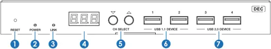

| No. | Name | Function Description |
| 1 | RESET | After powering on the device, press and hold the RESET button until the POWER LED and LINK LED flash at the same time, release the button to reset the device to factory settings. |
| 2 | POWER LED (Red) |
|
| 3 | LINK LED (Green) | Connection status LED.
|
| 4 | LED screen | Shows the selected Encoder ID as default. Displays the corresponding options of configuration functions during setting Decoder configurations. |
| 5 | CH SELECT | Used to set Decoder ID and other settings. |
| 6 | USB 1.1 DEVICE | Connect to USB 1.1 devices, such as Keyboard or Mouse. |
| 7 | USB 2.0 DEVICE | Connect to USB 2.0 devices, such as USB flash disk or USB Camera. |
| 8 | IR OUT | IR signal output port. The IR level can be set to 5V or 12V (default) through the panel buttons. |
| 9 | IR IN | IR signal input port. The IR level can be set to 5V or 12V (default) through the panel buttons. |
| 10 | RELAYS I DIGITAL IO | VCC: Power output (12V or 5V configurable), maximum to 12V@50mA, 5V@ 100mA loading. The default output is 12V. RELAYS: 2 channel low-voltage relay ports, each group is independent and isolated, maximum to 1A 30VDC loading. Contacts are disconnected by default. DIGITAL IO: 2 channel GPIO ports, for digital level signal output control or input detection (up to 12V level detection). The output control mode (default mode, low level as default output) or input detection mode is configurable. The DIGITAL IO internal pull-up voltage follows the VCC. Output control mode: a. The maximum withstand sink current is 50mA when outputting low level. b. When VCC is 5V and high level is output, the maximum current driving capacity is 2mA. c. When VCC is 12V and high level is output, the maximum current driving capacity is 5mA. Input detection mode: a. When VCC is 5V, DIGITAL IO is pulled up to 5V internally through a 2.2K ohm resistor. b. When VCC is 12V, DIGITAL IO is pulled up to 12V internally through a 2.2K ohm resistor. |
| 11 | RS-232 | RS-232 serial port, supporting RS-232 command pass-through and local serial port control. |
| 12 | AUDIO IN/OUT | AUDIO IN: Analog audio input port, the audio can be transmitted to Encoder AUDIO OUT in unicast mode (point-to-point direct connection). |
| AUDIO OUT: Analog audio output port. It outputs the same audio of that on HDMI OUT in case audio format is LPCM. | ||
| 13 | SPDIF IN | S/PDIF signal input port. |
| 14 | HDMI OUT | HDMI signal output port, connected to an HDMI display device such as TV or monitor. |
| 15 | FIBER | Connect with optical fiber module, and receive signals from the Encoder with an optical fiber cable directly or through a Switch. |
| 16 | LAN (POE) | 1G LAN port, connect network Switch to form a distributed system. Note: When network switch delivers POE power supply, DC 12V adapter doesn’t need to apply on the unit. |
| 17 | Data Signal Indicator lamp (Yellow) |
|
| 18 | Link Signal Indicator lamp (Green) |
|
| 19 | DC 12V | The device can be powered via two methods:
When the Switch supports POE function, DC power supply is not needed. |
Operation description of the LED screen and CH SELECT buttons (For Decoder).
1, ENC connection: After the system is powered on, the Decoder’s LED screen will show 000 by default if not set. Directly press the UP/DOWN button to select the channel ID of the connected Encoder (ID range: 000~762) to complete connection.
2, IP address: Press and hold the UP button for 5 seconds, the Decoder’s LED screen will show in sequence “IPx”, “xxx”, “xxx”, “xxx”, “xxx”, which are the IP mode and IP address of Decoder.
3, Configuration mode: Press and hold UP + DOWN buttons at the same time for 5 seconds, then release to enter the configuration mode with “CFN” displaying on the LED screen.
4, Device ID settings: After entering the configuration mode, press the UP/DOWN button to enter the first page with the current ID number (e.g. 001) displaying on the LED screen (000 by default). Press and hold UP + DOWN buttons for 5 seconds, then release to enter the ID settings mode, in which the ID number (e.g. 001) on the LED screen will flash at 1Hz, then press the UP/DOWN button to select the device ID you desired (ID range: 000~762), then press and hold UP + DOWN buttons for 5 seconds to confirm the setting and stop flashing. After setting, the unit will reboot automatically.
Note: The device ID can not be modified in Controller Box mode.
5, Output scaling settings: After entering the configuration mode, press the UP/DOWN button to enter the second page with “S00” (in which “S” refers to Scaling, and “00” to resolution ID) displaying on the LED screen (S00 by default). Press and hold UP + DOWN buttons for 5 seconds, then release to enter the settings mode, in which the Sxx on the LED screen will flash at 1Hz, then press the UP/DOWN button to select the ID you desired, then press and hold UP + DOWN buttons for 5 seconds to confirm the setting and stop flashing.
The scaling settings are listed below:
| Scaling Sxx | Resolution Description |
| S00 | bypass |
| S01 | 1080P50 |
| S02 | 1080P60 |
| S03 | 720P50 |
| S04 | 720P60 |
| S05 | 2160P24 |
| S06 | 2160P30 |
| S07 | 2160P50 |
| S08 | 2160P60 |
| S09 | 1280×1024 |
| S10 | 1360×768 |
| S11 | 1440×900 |
| S12 | 1680×1050 |
| S13 | 1920×1200 |
6, IR mode settings: After entering the configuration mode, press the UP/DOWN button to enter the third page with “IR2” (in which “IR” refers to IR and “2” to 12V) displaying on the LED screen (IR2 by default). Press and hold UP + DOWN buttons for 5 seconds, then release to enter the settings mode, in which the IR mode (IR1 or IR2) on the LED screen will flash at 1Hz, then press the UP/DOWN button to select the IR mode, then press and hold UP + DOWN buttons for 5 seconds to confirm the setting and stop flashing.
The corresponding IR mode options are as follows:
IR1: 5V IR wire
IR2: 12V IR wire
7, eARC/ARC or S/PDIF audio return settings: After entering the configuration mode, press the UP/DOWN button to enter the fourth page with “ARC/SPD” displaying on the LED screen (ARC by default). Press and hold UP + DOWN buttons for 5 seconds, then release to enter the audio return settings mode, in which the audio return mode (ARC/SPD) on the LED screen will flash at 1Hz, then press the UP/DOWN button to select the mode, then press and hold UP + DOWN buttons for 5 seconds to confirm the setting and stop flashing. The corresponding audio return mode options are as follows:
ARC: eARC/ARC audio return (The audio from the HDMI OUT port of Decoder is transmitted back to the HDMI IN port of the Encoder.)
SPD: S/PDIF audio return (The audio from the S/PDIF IN port of Decoder is transmitted back to the S/PDIF OUT port of the Encoder.)
Note:
(1) The audio return mode can not be modified through front panel buttons in Controller Box or Multicast mode.
(2) Only when both the Encoder and Decoder are set to C2C audio return mode, the eARC/ARC or S/PDIF audio return can be realized.
(3) When to use ARC, ARC audio amplifier on Encoder HDMI IN port and ARC TV on Decoder HDMI OUT port should be used.
When to use eARC, eARC audio amplifier on Encoder HDMI IN port and eARC TV on Decoder HDMI OUT port should be used.
8, IP mode settings: After entering the configuration mode, press the UP/DOWN button to enter the fifth page with “IP1/IP2/IP3” displaying on the LED screen (IP3 by default).
Press and hold UP + DOWN buttons for 5 seconds, then release to enter the settings mode, in which the IP mode (IP1/IP2/IP3) on the LED screen will flash at 1Hz, then press the UP/DOWN button to select the mode, then press and hold UP + DOWN buttons for 5 seconds to confirm the setting and stop flashing. After setting, the unit will reboot automatically.
The corresponding IP mode options are as follows:
IP1: Static IP mode (Default IP address: 169.254.100.253)
IP2: DHCP IP mode
IP3: Auto IP mode (Default assigned network segment: 169.254.xxx.xxx)
Note: The IP mode can not be modified in Controller Box mode.
9, Fiber/Copper mode settings: After entering the configuration mode, press the UP/DOWN button to enter the sixth page with “CPP/FIB” displaying on the LED screen (CPP by default). Press and hold UP + DOWN buttons for 5 seconds, then release to enter the settings mode, in which the Copper/Fiber mode (CPP/FIB) on the LED screen will flash at 1Hz, then press the UP/DOWN button to select the mode, then press and hold UP + DOWN buttons for 5 seconds to confirm the setting and stop flashing. After setting, the unit will reboot automatically.
The corresponding Fiber/Copper mode options are as follows:
CPP: Copper mode
FIB: Fiber mode
10, Multicast mode settings: After entering the configuration mode, press the UP/DOWN button to enter the seventh page with “CA1/CA2” displaying on the LED screen (CA1 by default). Press and hold UP + DOWN buttons for 5 seconds, then release to enter the settings mode, in which the Multicast mode (CA1/CA2) on the LED screen will flash at 1Hz, then press the UP/DOWN button to select the mode, then press and hold UP + DOWN buttons for 5 seconds to confirm the setting and stop flashing. After setting, the unit will reboot automatically.
The corresponding multicast mode options are as follows:
CA1: Unicast mode
CA2: Multicast mode
11, Audio return mode settings: After entering the configuration mode, press the UP/DOWN button to enter the eighth page with “C2C/A2A” displaying on the LED screen (C2C by default). Press and hold UP + DOWN buttons for 5 seconds, then release to enter the settings mode, in which the audio return mode (C2C/A2A) on the LED screen will flash at 1Hz, then press the UP/DOWN button to select the mode, then press and hold UP + DOWN buttons for 5 seconds to confirm the setting and stop flashing. After setting, the unit will reboot automatically.
The corresponding audio return mode options are as follows:
C2C: The eARC/ARC or S/PDIF audio from the Decoder is transmitted back to the HDMI IN or S/PDIF OUT port of the Encoder.
A2A: The analog audio embedded in the Decoder is transmitted back to the AUDIO OUT analog audio port of the Encoder.
Note:
(1) The audio return mode can not be modified through front panel buttons in Controller Box or Multicast mode.
(2) Only when both the Encoder and Decoder are correspondingly set to C2C/A2A audio return mode in unicast mode, the audio return can be realized.
(3) The A2A audio return mode is available only in unicast mode.
(4) When to use ARC, ARC audio amplifier on Encoder HDMI IN port and ARC TV on Decoder HDMI OUT port should be used.
When to use eARC, eARC audio amplifier on Encoder HDMI IN port and eARC TV on Decoder HDMI OUT port should be used.
(5) After entering various setting modes, you can hold down the DOWN button to exit the current interface quickly, or if you do not perform any operation within 5 seconds, it will automatically return to the previous interface.
5.3 IR Pin Definition

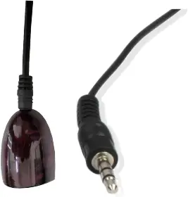
IR BLASTER IR RECEIVER
IR BLASTER
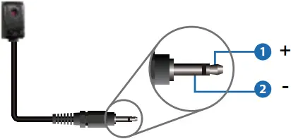
IR RECEIVER
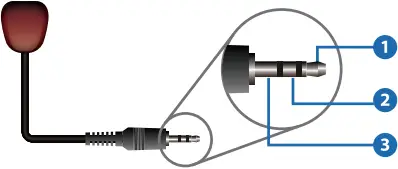
(1) IR Signal
(2) Grounding
(3) Power 12V
6. Rack Mounting Instruction
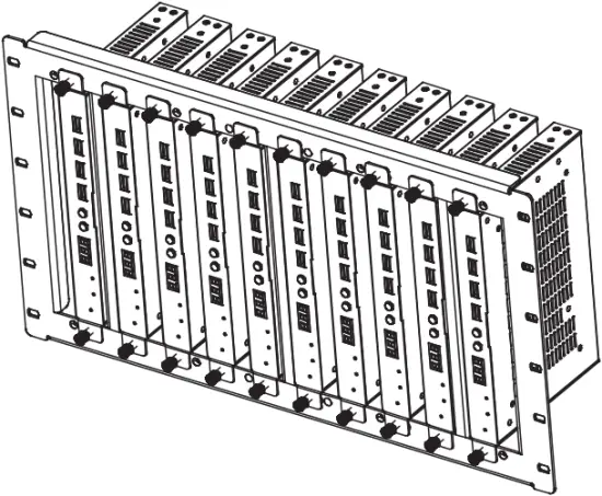
6.1 6U V2 Rack Mounting
This product can be mounted in a standard 6U V2 rack (Please contact your supplier for 6U V2 rack sale). The mounting steps are as follows:
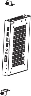
Step 1: Use included screws to fix two mounting ears on the product, as shown in the figure below:
Step 2: Insert the product with mounting ears into a 6U V2 rack (6/8/10 units can be installed vertically), as shown in the figure below:
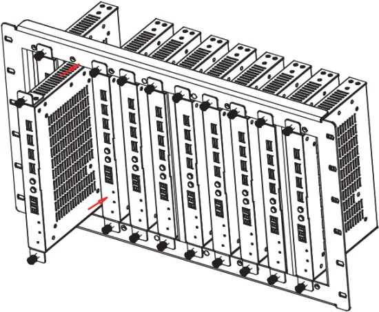
Step 3: Use screws to fix mounting ears on the rack to complete the mounting, as shown in the figure below:
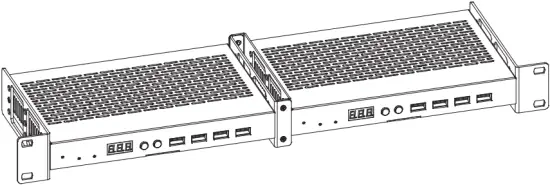
6.2 1U V2 Rack Mounting
This product also can be mounted in a standard 1U V2 rack (2 units can be installed horizontally). The mounting steps are as follows:
Step 1: Use included screws to fix two 1U V2 rack brackets on two products respectively, as shown in the figure below:
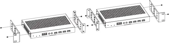
Step 2: Use screws to fix two 1U V2 rack brackets together, as shown in the figure below:

Step 3: Fasten screws between two 1U V2 rack brackets, so that two products are mounted in a 1U V2 rack, as shown in the figure below:
7. MJPEG Substream Operation Introduction
7.1 MJPEG Substream Preview/Configuration via Web Page
The product supports playing MJPEG Substream on computer through the corresponding software such as VLC media player, simultaneously you can access the Web page to configure the MJPEG Substream.
Follow the steps below to preview and configure the MJPEG Substream.
Step 1: Connect the Encoder, Decoder and PC to the same Switcher, then connect an HDMI source device and power supply. The connection diagram is shown as below.
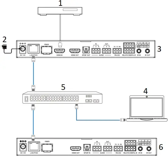
- Blu-ray Player
- Power Adapter
- Encoder
- PC
- 1G Ethernet Switch
- Decoder
Step 2: Install a bonjour protocol checking tool (such as zeroconfService Browser) on PC to find the IP address of the Encoder/Decoder.
Take zeroconfServiceBrowser as an example. After opening the software, you can select “Workgroup Manager” in Services of Browser, select the Host name in Service-Instances, and find the IP address in the Address item in of Instance-Info.
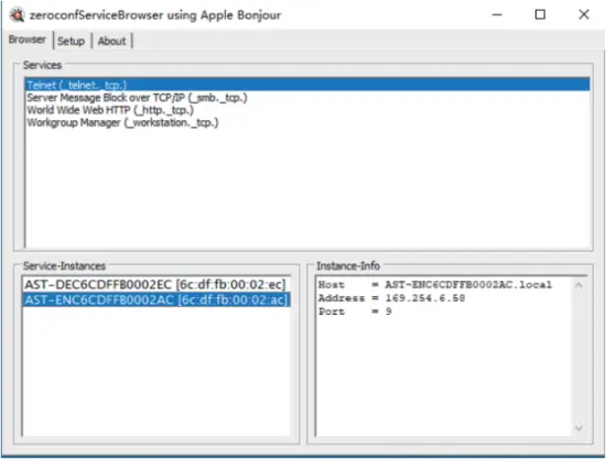
Note:
(1) The window in the lower left corner displays the Host names of all devices in the current network.
(2) The window in the lower right corner displays the Host name, IP address and Port number of the device.
(3) The Host name of Encoder starts with AST-ENC; the Host name of Decoder starts with AST-DEC.
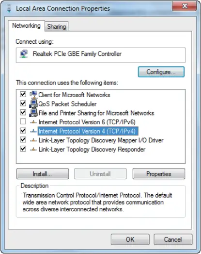
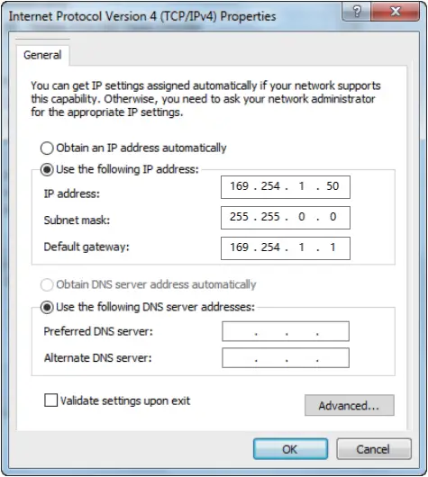
Step 3: Set the PC’s IP address to the same network segment with IP address of the Encoder/Decoder found in step 2.
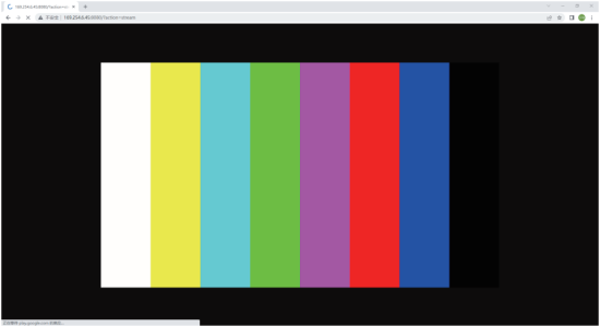
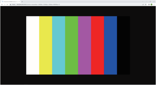
Step 4: According to the IP address of the Encoder/Decoder found through the bonjour protocol checking tool, input “http://IP:PORT/?action=stream” into the web browser on PC. The MJPEG Substream will be displayed with the default resolution, as shown in the figure below.
Step 5: Change the resolution of the obtained Encoder/Decoder IP address in the following format.
http://IP:PORT/?action=stream&w=x&h=x&fps=x&bw=x&as=x&mq=x
- WIDTH: [Optional] image width. In pixels. ‘x’ means no change.
Default is 640. - HEIGHT: [Optional] image height. In pixels. ‘x’ means no change.
Default is 360. - FRAMERATE: [Optional] frame rate of sub-stream.
Unit: fps (frame per second). ‘x’ means no change. Default is 30. - BW: [Optional] maximum bandwidth of sub-stream traffic.
Unit: Kbps (Kbits per second). ‘x’ means no change. Default is 8000 (8Mbps). - AS: [Optional] aspect ratio configuration. ‘x’ means no change. Default is 0.
- 0: extend to what “WIDTH” and “HEIGHT” configured
- 1: [A1 only] keep original aspect ratio and place in the center of output (letterboxing or pillarboxing)
- MINQ: [Optional] minimum image quality number. Range: 10, 20, …, 90, 100, higher setting means better image quality. ‘x’ means no change. Default value is 10. Limit driver auto bandwidth control’s minimum quality number. If quality lower then MINQ value, the driver will drop frame by returning 0 size file.
After changing, input the new Encoder/Decoder IP address into the web browser on PC, the MJPEG Substream will be displayed with the desired resolution, as shown in the figure below.
7.2 VLC Media Player Instruction
Firstly, perform the step 1~3 as described in Chapter 7.1, then open the VLC media player on PC. Please see the following icon.

Click “Media > Open Network Stream”
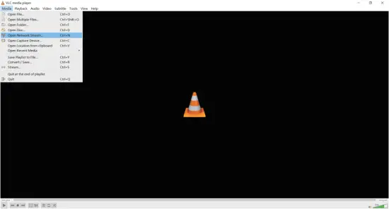
After clicking the “Open Network Stream” option, the following page will appear.
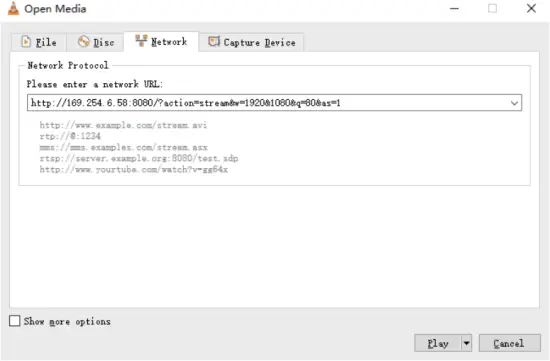
Enter the MJPEG Substream network URL, then click “Play” button.

Choose “Tools>Codec information“, a pop-up window will display and show you Stream information, as shown in the figure below.
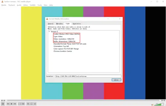
Choose “Tools>Codec information>Statistics” to check current Bitrate. Please see the following picture.

Note: The Bitrate is floating up and down when you check it. This is a normal phenomenon.
8. Switch Model
A network Switch used to set up the system should support below features:
- Type of layer 3/managed network Switch.
- Gigabit bandwidth.
- 8KB jumbo frame capability.
- IGMP snooping.
The following Switch models are highly recommended.
| Manufacturer | Model Number |
| CISCO | CISCO SG500 |
| CISCO | CATALYST series |
| HUAWEI | S5720S-28X-PWR-LI-AC |
| ZyXEL | GS2210 |
| LUXUL | AMS-4424P |
9. 4K over IP System Control
This product can be controlled by Controller Box or third-party controller. For details of 4K over IP system control, please refer to the user manual of “Video over IP Controller”.
10. Application Example
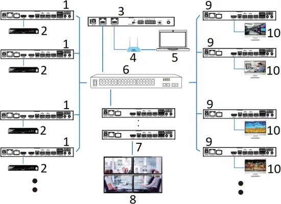
- ENC
- DVD
- Controller Box
- Router (optional)
- PC
- 1G Ethernet Switch
- 4 × DEC
- Video Wall
- DEC
- TV
Note:
(1) For the default IP mode of Control LAN port of the Controller Box is DHCP, the PC also needs to be set to “Obtain an IP address automatically” mode, and a DHCP server (e.g. network router) is required in the system.
(2) If there is no DHCP server in the system, 192.168.0.225 will be used as the IP address of Control LAN port. You need to set the IP address of the PC to be in the same network segment. For example, set PC’s IP address as 192.168.0.88.
(3) You can access the Web GUI by inputting Control LAN port IP address (192.168.0.225) or URL “http://controller.local” on your computer’s browser.
(4) No need to care about settings of Video LAN port of the Controller Box, they are managed by Controller automatically (Default).
(5) When the Network Switch does not support PoE, the Encoder, Decoder and Controller Box should be powered by DC power adapter.
![]()
The terms HDMI and HDMI High-Definition Multimedia interface, and the HDMI Logo are trademarks or registered trademarks of HDMI Licensing LLC in the United States and other countries.
Customer Service
The return of a product to our Customer Service implies the full agreement of the terms and conditions hereinafter. There terms and conditions may be changed without prior notice.
1) Warranty
The limited warranty period of the product is fixed three years.
2) Scope
These terms and conditions of Customer Service apply to the customer service provided for the products or any other items sold by authorized distributor only.
3) Warranty Exclusion:
- Warranty expiration.
- Factory applied serial number has been altered or removed from the Product.
- Damage, deterioration or malfunction caused by:
✓ Normal wear and tear.
✓ Use of supplies or parts not meeting our specifications.
✓ No certificate or invoice as the proof of warranty.
✓ The product model showed on the warranty card does not match with the model of the product for repairing or had been altered.
✓ Damage caused by force majeure.
✓ Servicing not authorized by distributor.
✓ Any other causes which does not relate to a product defect. - Shipping fees, installation or labor charges for installation or setup of the product.
4) Documentation:
Customer Service will accept defective product(s) in the scope of warranty coverage at the sole condition that the defeat has been clearly defined, and upon reception of the documents or copy of invoice, indicating the date of purchase, the type of product, the serial number, and the name of distributor.
Remarks: Please contact your local distributor for further assistance or solutions.
Documents / Resources
 |
VIVO LINK JPEG2000 AVoIP Encoder and Decoder [pdf] User Manual VLVWIP2000-ENC, VLVWIP2000-DEC, JPEG2000 AVoIP Encoder and Decoder, JPEG2000, AVoIP Encoder and Decoder, Encoder and Decoder, and Decoder |