![]() Instructions for Use
Instructions for Use
Vishay Sfernice
WLMO2LD Sfernice Wireless Device
Series WLMO
Ed 00, 2025-03 SIM/HER
Wireless position data transfer module
Battery powered
Long Range and Low Power Communication
The instructions for use contain all required information for fast commissioning and safe operation of Vishay Sfernice motion transducers.
Caution: Information included in product datasheets leads to the general information given in this Application Note.
Before installing, configurating or operating the WLMO or performing any maintenance activities associated with it, read these instructions carefully§
Introduction
1.1. What is LoRa® protocol?
WLMO has been developed and qualified to be used in industrial application in standard condition defined in technical specification of the product. The module can endure outdoor usage in environmental conditions defined in technical specification of the product.
This product uses LoRa® as protocol of communication. LoRa® is a wireless modulation technique derived from Chirp Spread Spectrum (CSS) technology. It encodes information on radio waves using chirp pulses. LoRa® modulated transmission is robust against disturbances and can be received across great distances (Fig. 1).
 Fig. 1 : Bandwith vs Range for different kind of communication – thethingsnetwork.org
The LoRa® mark and LoRa® logo are trademarks of Semtech Corporation
1.2. Specifications
Data transmission specifications:
- Frequency: 2.4 GHz
- Power emission: 7.1mW (+8.5 dBm) max.
- Receiving sensitivity: -140 dBm
Battery:
- Supply: 2 x AAAA 1.5V 625mAh battery
Mechanical:
- D8 3 male poles connectors
- Oblong holes for fixation
Environment:
- Waterproof: IP67
- UV resistant
- Storage and operations temperature: -18 °C / + 55 °C
Certifications:
- CE conformity
- FCC (USA): 2BKGFWLMO2LD
- IC ID (Canada): 33601-WLMO2LD
1.3. Main features
- Integrated antenna
- 2 channels for motion sensors
- Temperature monitoring (1 °C step)
- Wireless Range up to 2 km in open fields
- Supply by batteries AAAA (Replaceable)
- Transmitter and receiver mode: Configurable by dedicated software
- Estimated autonomy: 2 Years with configuration 6 measures per hour 1 transmission per hour
Mounting instructions
A Vishay Sfernice WLMO is a precision instrument; to make the best use of the antenna, the user must respect Vishay Sfernice cautions about the good mounting of the product. Therefore, avoid applying external mechanical force to the product.
2.1. Mounting type
The housing of WLMO includes flange to allow the fixation by screws:

We recommend using 2 screws D4 mm (ISO4762) with Pan-Head with support washer (ISO7089).
![]() WARNING
WARNING
Before mounting the WLMO:
- Always wear protective clothing, gloves, and eyewear when performing any installation procedures to avoid personal injury or property damage.
- Check with your process or safety engineer for any additional measures that must be taken to protect the product
![]() Notice
Notice
Device damage:
Torque on screws regarding plastic mounting bracket. The maximum torque of the mounting plate must not be exceeded 30 cN.m
2.2. How to set up the module in the good direction
The device integrates a 2D antenna on its printed circuit board. It means this antenna is directive.
The following pictures represent the advised orientations of the WLMO module to emit to a three-dimensional 2.4GHz gateway antenna to get the best radiocommunication range:
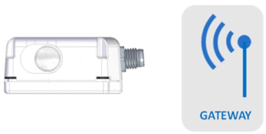 Horizontal orientation – connectors to the gateway Horizontal orientation – connectors to the gateway |
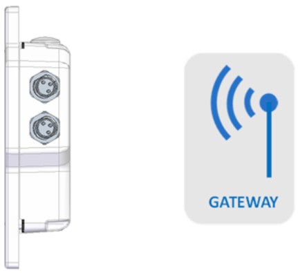 Vertical orientation – connectors upwards Vertical orientation – connectors upwards |
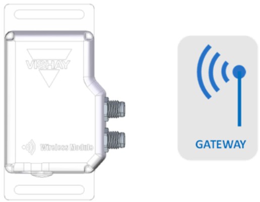 Lateral orientation – connectors to the gateway Lateral orientation – connectors to the gateway |
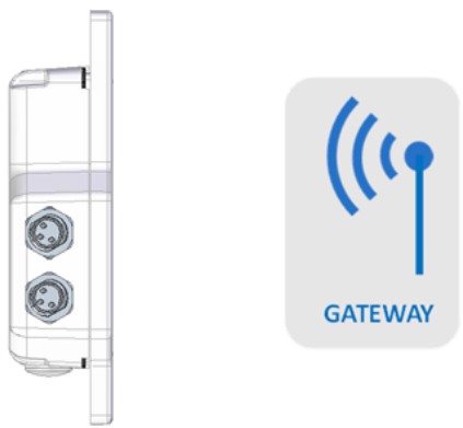 Vertical orientation – connectors downwards Vertical orientation – connectors downwards |
Electrical connection
3.1. Output device
The output devices are two D8 connectors. Each connector has three male pins. The user needs specific connectors to connect sensors to the module, Vishay Sfernice offers a large range of position sensors equipped with this kind of connector.
3.2. Diagram of functions

3.3. Pin Mapping on diameter 8mm 3 pins connector

| PIN 1 | +5Vdc |
| PIN 3 | GND |
| PIN 4 | Sensor signal |
Electrical parameters and performance
4.1. Caution of installation for the user
The module has to be placed in service only by technical personnel under observance of all relevant safety regulations.
Non-observance of the installation instructions will cancel any guaranty or liability claims.
All personal protection measures in case of a transducer defect or failure must be taken before startup.
The specified supply voltage is to be applied only at the relevant terminals.
Non-observance of output configuration could result in destruction of the device and loss of guaranty.
Admissible supply condition and protection are defined by technical datasheet.
4.2. Startup of the device
WLMO has to be activated by the rubber button situated on one face of the housing. By pushing this button for 2 seconds, the user starts the module, a green light appears through the button, it gives the information to the user.
To launch the pairing of the module, the user has to push the button for around 7 seconds. A blue flashing light indicates the module is ready to be paired.
The module can be put on stand-by over the air.
By pushing this button for 2 seconds the user turns off the module, a red light appears through the button, it gives the information to the user. The shutdown can be done over the air too.
4.3. Range of the signal
The maximum range of the signal is estimated to be 2 kilometers. This value can be reached in the following conditions:
- Data transmission is in an open field, there is no obstacle between WLMO and the receiver.
- The spreading Factor is set at 12.
- The WLMO is oriented in the 3 positions described in the section “2.2 How to set up the module in the good direction”
LoRa® modulation has a total of 6 spreading factors from SF7 to SF12. Spreading factors influence data rate, time-onair, battery life, and receiver sensitivity. The spreading factor controls the chirp rate and thus controls the speed of data transmission. Lower spreading factors mean faster chirps and therefore a higher data transmission rate.
4.4. Autonomy of batteries
The life of battery is estimated at 2 years. This value can be reached in the following conditions:
- Cautious taken with the storage of the product.
- Full batteries delivered.
- 1 measure every 15 minutes and 1 transmission per hour.
- The spreading Factor is set at 7
4.5. Replacement of batteries
The user can change batteries himself by taking screws out. The replacement must be done with the same kind of batteries:
2 x AAAA 1.5V 625mAh battery. User must be very cautious in the reassembly of the product: there is a seal which makes the product IP67.
To open the WLMO, put the device upside-down on a workbench and remove the 4 screws counterclockwise from the screw holes using a Philips screwdriver (screw drives by cross recess H Philips).
The LoRa® mark and LoRa® logo are trademarks of Semtech Corporation
![]() CAUTION
CAUTION
Do not open WLMO within a hazardous area to replace the battery. The device can be only opened in a workshop equipped to handle electronic components.
![]() NOTICE
NOTICE
Loss of Ingress Protection IP67:
Make sure that before closing WLMO, the seal is positioned correctly.
![]() NOTICE
NOTICE
Risk of damaging the electronics.
When opening the WLMO, avoid touching the electronic circuits and the green PCB (Printed Circuit Board) to avoid damage. Always ensure you are discharged of static electricity by wearing an antistatic wrist strap band.
LORA® communication and Commands
5.1. Gateway requirements
The Gateway must be a LoRa® 2.4GHz radiofrequency device (SX1280 Semtech chip inside for example).
At the first start, the WLMO node has factory settings.
To get the first frames from WLMO, the GATEWAY must be set on these parameters:
Channel: CH0 = 2.402GHz
Bandwidth: 400kHz
Spreading Factor: SF7
Configure your PANID (Personal aera network ID) with 5 digits (ex: PANID = “57001”)
The Gateway must be set in listening mode to intercept the broadcasted “PAIRING FRAME” from the WLMO.
5.2. Turn On and Pairing
The WLMO module is initially off.
Press the button for 7 seconds until it continuously flashes blue.
Now, the module is broadcasting its PARING packets to the network on SF7, for 2 minutes until the pairing is done.
This frame is broadcasted on 5 channels.
The frame of the WLMO is composed by a uint8_t buffer [14], the buffer is AES128 encrypted:
| Byte position | Format | Length in byte | Value range | Example value | Designation |
| 0 | uint8_t | 1 | 0x11 | 0x11 | Frame direction: WLMO to Gateway |
| 1 | uint16_t | 2 | 1 – 65534 | 0xFF 0xFF |
PANID (personal aera network identification number) 0xFFFF here means new PANID requested for pairing |
| 3 | uint32_t | 4 | 0 – 4 294 967 295 |
0x95 0x5E 0x86 0x8A |
WLMO ID (device identification number) “2 506 000 010” here for example |
| 7 | uint8_t [3] | 3 | “VSY” | ‘V’ ‘S’ ‘Y’ |
“VSY”: identify Vishay WLMO product frame |
| 10 | uint8_t | 1 | 0 – 255 | 1 | paring frame identification |
| 11 | uint8_t | 1 | 0 – 1 | 1 | 1: request acknowledgement for pairing |
| 12 | uint8_t | 1 | 0 – 32 | 0 | 0: payload size in byte |
| 13 | uint8_t | 1 | 0 – 255 | 0xFF | Checksum of the buffer |
The frame must be AES128 decrypted. Then the checksum must be verified during data reading.
The gateway must read this frame to get data of the WLMO and to answer for pairing.
The module is in this PAIRING mode until the Gateway responds with an acknowledgement packet structured as below:
Example of pairing a #2506000010 WLMO to a 57001 (0xDE49) PANID network.
| Byte position | Format | Length in byte | Value range | Example value | Designation |
| 0 | uint8_t | 1 | 0 – 255 | 0x01 | Frame direction: Gateway to WLMO |
| 1 | uint16_t | 2 | 1 – 65534 | 0xFF 0xFF |
Initial broadcasted PANID |
| 3 | uint32_t | 4 | 0 – 4 294 967 295 | 0x95 0x5E 0x86 0x8A |
WLMO ID (device identification number) “2506000010” decimal value here for example |
| 7 | uint8_t [3] | 3 | VSY | ‘V’ ‘S’ ‘Y’ |
“VSY” to identify Vishay WLMO product frame |
| 10 | uint8_t | 1 | 0 – 255 | 1 | paring frame identification (same as received by the gateway from WLMO) |
| 11 | uint8_t | 1 | 0 – 1 | 1 | 1: request acknowledgement for pairing COM_RF_TX_REQUEST_ACK_PAIRING |
| 12 | uint8_t | 1 | 0 – 40 | 2 | 2 is the payload size to send a new PANID to the WLMO |
| 13 | uint8_t | 1 | 0 – 255 | 0xA9 | Lower hex part of “57001” PANID (MSB hex: 0xDEA9) |
| 14 | uint8_t | 1 | 0 – 255 | 0xDE | Upper hex part of “57001” PANID (MSB hex: 0xDEA9) |
| 15 | uint8_t | 1 | 0 – 255 | 0xFF | Checksum of the buffer |
The frame must be AES128 encrypted before transmission.
The gateway must read this frame to get data of the WLMO and to answer for pairing.
At the time the WLMO receives this PAIRING acknowledgement packet, it validates it.
Once the module is paired, the node starts to flash green once.
Then the WLMO starts to send periodic measurement packets as decrypted and described below:
WLMO is in listening mode for 60 seconds after validation of pairing.
5.3. LoRa® Frame interpretation & packets
The Gateway must be set in listening mode to intercept the broadcasted “Measurement FRAMES” from the WLMO.
When the WLMO is paired, it periodically sends measurement packets as decrypted and described below:
| Byte position | Format | Length in byte | Value range | Example value | Designation |
| 0 | uint8_t | 1 | 0 – 255 | 0x11 | Frame direction: WLMO to Gateway |
| 1 | uint16_t | 2 | 1 – 65534 | 0xA9 0xDE |
“57001” PANID (MSB hex: 0xDEA9) |
| 3 | uint32_t | 4 | 0 – 4 294 967 295 | 0x95 0x5E 0x86 0x8A |
WLMO ID (device identification number) “2506000010” decimal value here for example |
| 7 | uint8_t [3] | 3 | VSY | ‘V’ ‘S’ ‘Y’ |
“VSY” to identify Vishay WLMO product frame |
| 10 | uint8_t | 1 | 0 – 255 | 1 | paring frame identification |
| 11 | uint8_t | 1 | 0 – 1 | 0 | 0: uplink frame transceiver |
| 12 | uint8_t | 1 | 1 – 40 | 35 | 35 is an example of the payload SIZE sent by the WLMO |
| 13 | uint8_t | 40 max. | 0 – 255 | Payload | |
| 14+SIZE | uint8_t | 1 | 0 – 255 | 0xFF | Checksum of the buffer |
Example of the payload:
“#250600001,291,2.500,2.500,21,3.249”
“#identity, measurement number, ADC1 value, ADC2 value, temperature, battery voltage”
| Data number | Format | Data length In byte | Example value | Designation |
| 0 | ASCII | 9 | 123456789 | ID du device |
| 1 | ASCII | 5 | 00042 | Frame number |
| 2 | Double | 8 | 3.456 | Voltage level of ADC output sensor 1 |
| 3 | Double | 8 | 1.234 | Voltage level of ADC output sensor 2 |
| 4 | Int | 4 | 25 | Temperature in Celsius degree |
| 5 | Double | 8 | 3.75 | Battery voltage |
5.4. General commands over the air
The following requests and settings are also available over the air. The WLMO module must be paired with the gateway. Then the “Commands” must be written in the payload as bellow:
| Designation | Command to send by the payload | Value range of X | Comments | |
| Acknowledgement of a measurement frame | #ID,ACK=X\n | 0 – 60 sec | – | |
| Read the current temperature | #ID,CT\n | – | – | |
| Read the sensor #1 value | #ID,CV1\n | – | – | |
| Read the sensor #2 value | #ID,CV2\n | – | – | |
| Read the sensor #1 voltage value | #ID,CADC1\n | – | – | |
| Read the sensor #2 voltage value | #ID,CADC2\n | – | – | |
| Read the 5 last sensor #1 values | #ID, L5V1\n | – | – | |
| Read the 5 last sensor #2 values | #ID, L5V2\n | – | – | |
| Read the battery voltage | #ID,BAT\n | – | – | |
| Define the period of emission of sensor values | #ID,PER=X\n | 20 – 10 000 sec | – | |
| Read the emission period of the sensor values | #ID,PER?\n | 20 – 10 000 sec | – | |
| Set the sensor activation status #1 | #ID,ENA1=X\n | 0 – 1 | – | |
| Set the sensor activation status #2 | #ID,ENA2=X\n | 0 – 1 | – | |
| Define the number of measurements between two emission periods. | #ID,ACNT=X\n | 1 – 10 000 | ||
| Read the number of measurements between two emission periods. | #ID,ACTN?\n | 1 – 10 000 | Initially 4 measurements per transmission | |
| Read the sensor activation status #1 | #ID,ENA1?\n | 0 – 1 | – | |
| Read the sensor activation status #2 | #ID,ENA2?\n | 0 – 1 | – | |
| Set LoRa® SF | #ID,SF=x\n | 7 – 12 | RESET: #identity, RST/n reset the WLMO to make the setting applied | |
| Read LoRa® SF | #ID,SF? \n | 7 – 12 | – | |
| Set the LoRa® radio channel | #ID,CH=X\n | 0 – 4 | – | |
| Request LoRa® radio channel | #ID,CH?\n | 0 – 4 | CH0 = 2.402 GHz | CH1 = 2.426 GHz |
| CH2 = 2.450 GHz | CH3 = 2.465 GHz | |||
| CH4 = 2.480 GHz | ||||
| Put the radio module in standby mode for a defined time | #ID,SSTBY=X\n | 0 – 36 000 sec | – | |
| Reset the radio module | #ID,RST\n | – | – | |
| Turn off the radio module | #ID,PWOFF\n | – | – | |
Environmental conditions of use
6.1. Temperature
The product has been designed to use under the conditions defined in the technical data sheet. If a specific environment requires rapid temperature changes, it must be validated by our technical services.
6.2. Sealing & Humidity
The level of sealing is indicated by the technical data sheet. General condition according to standard CEI. 60529.
6.3. Pressure
By the technology used our product is not sensible to the condition of pressure.
In case of unusual conditions please contact us for further information.
6.4. Shocks
The product has been designed to be used under the conditions defined in the technical specification. The performance will be reached only if the mounting instructions are respected.
6.5. Chemical attack
The external materials used have been chosen to ensure the integrity of our product in a normal environment of use of this type of product.
6.6. Magnetic fields
By the technology used our product is not sensible to strong magnetic or electromagnetic fields nearby.
Shelf Life
7.1. General storage and transportation recommendation
Careful attention must be paid when the components are stored before usage. Because high and very low environmental temperature, high humidity, corrosive gases, etc. might affect the solderability of the terminals and the function of the package.
Listed below are notes to be observed:
- Keep product in its original packaging.
- Do not store them within the vicinity of any corrosive gases such as hydrogen sulphide, sulphurous acid, chlorine or ammonium. The oxidation of the metals caused by such toxic gases may affect solderability.
- Exposure to direct sunlight and dust must be avoided.
- Storage temperatures are defined by technical datasheet.
![]() CAUTION
CAUTION
Insufficient protection during storage:
The packaging only provides limited protection against moisture and infiltration. Provide additional packaging as necessary
![]() Notice
Notice
Condensation in the device
Damage to device through formation of condensation if the temperature difference between transportation or storage and the mounting location exceeds 20 °C (36 °F).
- Before taking the device into operation let the device adapt for several hours in the new environment.
7.2. Inspection or control before use
The product can be stored for 2 years and used without any additional control. Beyond this period, the product has to be verified before use on its main parameters, (linearity, electrical stroke).
7.3. Disposal
![]() Notice
Notice
Devices described in this manual should be recycled. They may not be disposed of in the municipal waste disposal services according to the Directive 2012/19/EC on waste electronic and electrical equipment (WEEE).
Devices can be returned to the supplier within the EC, or to a locally approved disposal service for eco-friendly recycling. Observe the specific regulations valid in your country.
CERTIFICATIONS
This device is intended for professional use only
8.1. United States FCC
This device complies with part 15 of the FCC Rules. Operation is subject to the following two conditions:
- This device may not cause harmful interference
- This device must accept any interference received, including interference that may cause undesired operation.
NOTE: The grantee is not responsible for any changes or modifications not expressly approved by the party responsible for compliance. Such modifications could void the user’s authority to operate the equipment.
A class equipment:
NOTE: This equipment has been tested and found to comply with the limits for a Class A digital device, pursuant to part 15 of the FCC Rules. These limits are designed to provide reasonable protection against harmful interference when the equipment is operated in a commercial environment. This equipment generates, uses, and can radiate radio frequency energy and, if not installed and used in accordance with the instruction manual, may cause harmful interference to radio communications.
Operation of this equipment in a residential area is likely to cause harmful interference in which case the user will be required to correct the interference at his own expense.
RF Exposure Compliance:
This equipment complies with FCC radiation exposure limits set forth for an uncontrolled environment and meets the FCC radio frequency (RF) Exposure Guidelines. This equipment should be installed and operated keeping the radiator at least 20 cm or more away from person’s body.
8.2. Canada ISED
This device contains license-exempt transmitter(s)/receiver(s) that comply with Innovation, Science and Economic Development Canada’s license-exempt RSS(s). Operation is subject to the following two conditions:
- This device may not cause interference.
- This device must accept any interference, including interference that may cause undesired operation of the device.
RF Exposure Compliance:
This equipment complies with ISED radiation exposure limits set forth for an uncontrolled environment and meets the RSS-102 of the ISED radio frequency (RF) Exposure rules. This equipment should be installed and operated keeping the radiator at least 20 cm or more away from person’s body.
For technical questions, contact: Sferprecisionpot@vishay.com
THIS DOCUMENT IS SUBJECT TO CHANGE WITHOUT NOTICE. THE PRODUCTS DESCRIBED HEREIN AND THIS DOCUMENT ARE SUBJECT TO SPECIFIC DISCLAIMERS, SET FORTH AT www.vishay.com
![]()
Documents / Resources
 |
VISHAY WLMO2LD Sfernice Wireless Device [pdf] Instruction Manual WLMO2LD, WLMO2LD Sfernice Wireless Device, Sfernice Wireless Device, Wireless Device |