Vimark 4700ZT Extractor Fans Zone 1 Extractor Fan with Timer
| 4700ZT | 4” (100mm) Zone 1, Timer | 4660P | 6″ Extractor Fan Pullcord |
| 4700ZTH | 4” (100mm) Zone 1, Timer & Humidistat |
4661P | 6″ Extractor Fan Pullcord Timer |
| 4600P | 4″ Extractor Fan Pullcord | 4750S | 4” (100mm) Inline Axial Fan |
| 4601P | 4″ Extractor Fan Pullcord Timer |
4751T | 4” (100mm) Inline Axial Fan Timer |
| 4720Z | 4” Zone 1 Flat Fascia Extractor Fan | 4720ZT | 4” Zone 1 Flat Fascia Extractor Fan with Timer |
Safety Instructions And Installation Notes
Safety Instructions
- Always switch off the electrical supply before commencing installation.
- This fan must be connected via a DP connection unit which is fitted with a 3A fuse.
- This fan must be installed using fixed wiring. A flexible cable should not be used.
- Connect to a 240V ac electrical supply. This extractor fan is double insulated and does not require an earth.
- Please note the IP (Ingress Protection) rating of this product when deciding the location for installation.
- Tis product is class II double insulated
- This extractor fan must be installed in accordance with the current edition of the IET Wiring Regulations and Building Regulations, BS 7671.
Installation Notes
- When installing this fan through an external wall, an external grille must be fitted at all times.
- The extractor fan must be mounted on flat surface.
- The extractor fan should be installed a minimum of 1.8m from the floor.
- For the best results, the extractor fan should be fitted as high as possible on the wall.
If in doubt, contact a qualified electrician
Product Features
Timer Fans
Timer fans are designed to be connected to the lighting circuit so that they will operate when the light is switched on, and stay on for a pre-set time after the light has been switched off.
Timer and Humidistat Fans
Timer and Humidistat fans are designed to be connected to the lighting circuit and will operate when either the light is switched on or when the humidity level exceeds the pre-set level between 60 and 90%.
Once the light is switched off, or the humidity level drops below the pre-set level, the fan will stay on for the time period set by the timer control, between 2 -30 minutes.
Noise Level
All ventilations fans have a low noise level, under 35dB.
Thermal Fuse
All Vimark ventilation fans have a thermal fuse which prevents the motor overheating if the impeller becomes jams.
Installation Instructions
- Switch off the mains supply before commencing the installation.
- Drill a hole in the wall to suit the fan and ducting: 4” fan Ø 110mm hole max.
If mounting the fan on the ceiling, position the fan between the joists - Route ducting from the fan position to the external grille position, ensuring the end of the ducting is flush to the walls. Ducting runs should be as short as possible for optimum performance.
- Remove the front cover of the fan by undoing the securing screw on the bottom edge. To access the cover on the Flat Facia fans remove the front plate first by pulling away from the pillars in each corner.
- Hold the body of the fan in position and mark on the wall/ceiling the four fixing screw positions and the cable entry hole.
- Drill and plug the wall/ceiling.
- Route the cable so that it exits through the wall ceiling at the position marked, leaving enough cable protruding so it can be terminated.
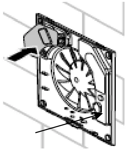
- Fix the fan body in position.
- Terminate the cable. (For Zone 1 fan the internal cover must be removed to access the terminal block)
- Fit the front cover and tighten the securing screw.
- Switch on and check for correct operation.
Ventilation Fan Performance
Vimark ventilation fans are design to meet the requirements of The Building Regulations – Approved Document F1 Means of Ventilation, and The Building Standards (Scotland) – Domestic Ventilation.
These Building Regulations and the Domestic Building Services Compliance Guide state the intermittent extract ventilation fans should have a specific fan power (SPF) less than 0.5W/(ltr/sec). Vimark fans meet this requirement.
Fan Positioning
Vimark ventilation fans are designed to move air over short distances, typically under 2m, and are suitable for through wall installations. These ventilation fans can also be installed in ceilings with the ducting length under 2m.
The ventilation fan should always be sited in the wall or located on the ceiling furthest from the main source of air replacement, e.g. door, to ensure optimum performance. The fan should also be located as high as possible.
Wiring
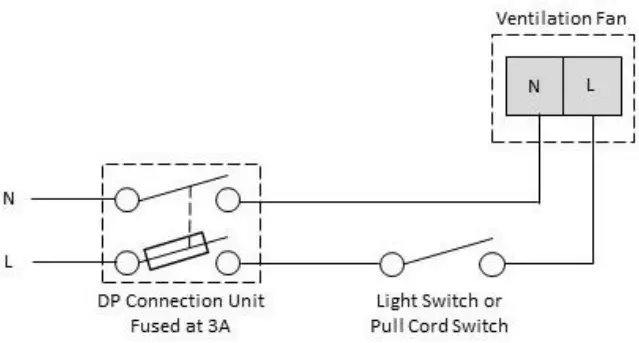
Standard Fan
The standard fan can be connected to the lighting circuit and controlled from a switch so that it only operates when the switch is on. The fan must be fed by a DP switched connection unit fitted with a 3A fuse. See Fig. 1.
The connections for this fan are:
L permanent live
N neutral
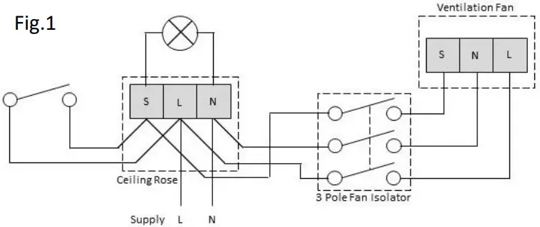
Timer Fans and Humidistat Fans
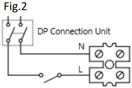
The timer fan can be connected to the lighting circuit. The circuit for this fan must be protected by a 3A device and should be controlled by a 3 pole fan isolator. See Fig. 2.
The connections for this fan are:
L permanent live
S switch live
N neutral
In-Line Axial fan
The In-Line Axial fan can be connected to the lighting circuit and controlled from a switch so that it only operates when the switch is on. The fan must be fed by a DP switched connection unit fitted with a 3A fuse. See Fig. 3.
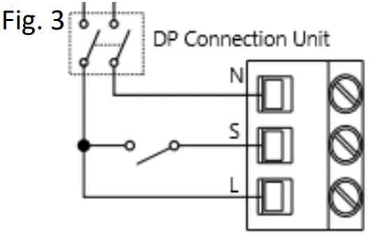
The connections for this fan are:
L permanent live
N neutral
S or LT Switch Live
Control Adjustments
The timer and humidistat and timer fans are supplied with an insulated screwdriver located inside the fan for adjusting the controls, which is clipped to the fan body.
Timer
The timer is adjustable from approximately 2 minutes to 30 minutes. The timer is factory set at approximately 15 minutes. Turn the control clockwise to increase the on time. Timers should be set for 15 minutes minimum.
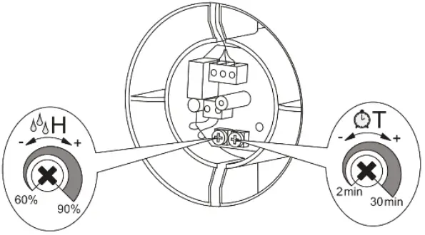
Humidistat
The humidistat range is approximately 60 – 90% relative humidity. The humidistat is factory set at approximately 75%. Turn the control clockwise to increase humidity.
Zone 1 Fans
To access the terminals and dials in the zone 1 fans remove the rubber cap on the right of the fan and the plastic terminal cover on the top left.
When dials are set to the required setting and the cables are securely terminated replace the cap/cover to maintain the IP rating.
General
This product should be recycled in the correct manner when it reaches the end of its life. Check local authorities for where facilities exist.
Clean with a soft dry cloth only, do not use aggressive cleaning products or solvents which may damage the product.
This product has a 3 year warranty from the date of purchase.
Specification
| Voltage | 220 – 250V ac 50Hz | Extraction Rate Zone 1 Fan 4” | 97m3 /hr (27 ltr/sec) |
| Hole cutout dimensions | Ø 110mm hole max. | Extraction Rate 4” Flat Fascia | 85m3 /hr (23 ltr/sec) |
| Insulation Class | Class II | Extraction Rate 4” inline Axial | 137m3 /hr (38 ltr/sec) |
| Timer Adjustment | 2 – 30 minutes | IP Rating | IP 44 (Zone 1 Fan IP X4) |
| Humidistat Adjustment | 60 – 90% humidity | Compliance | BS EN 60335-2-80 |
Customer Support
Deta Electrical Company Limited
UK: Panattoni Park, Luton Road, Chalton, Bedfordshire, LU4 9TT
EU: Unit 16 Ashbourne Ind. Est. Ashbourne, Co. Meath A84 W972 Ireland deta.co.uk Technical Helpline: +44 (0)1582 544 548


Documents / Resources
 |
Vimark 4700ZT Extractor Fans Zone 1 Extractor Fan with Timer [pdf] Installation Guide 4700ZT, 4700ZTH, 4600P, 4601P, 4720Z, 4660P, 4661P, 4750S, 4751T, 4720ZT, 4700ZT Extractor Fans Zone 1 Extractor Fan with Timer, 4700ZT, Extractor Fans Zone 1 Extractor Fan with Timer, Zone 1 Extractor Fan with Timer, Extractor Fan with Timer, Fan with Timer, with Timer |